


25
The Symbol toolbar
To create programs you need to place appropriate symbols onto the edit area, enter the correct control
commands into the symbols and then finally connect the symbols together to specify the flow of the
program.
Selection – this icon must before active before any selection can take place. It is normally
active unless Flow Line is selected. See page 30.
Start – a start symbol is required for the beginning of a flowchart or for a procedure that
will be called up by the main program. See page 30.
Output – use this symbol to turn an output or motor ON or OFF or to add a sound.
Process – use ‘wait’ for the time that an output should be switched on, ‘procedure’ for the
flowchart to call up a procedure or ‘make’ to set up a variable. See page 34.
Decision – used when a question must be asked to decide what to do next. It will check
for feedback from an input (switch or sensor) or the value of a variable to decide YES –
do this or NO – do that. See page 38.
Stop – use to end a flowchart or procedure. See page 41.
Flow Line - use to connect symbols together in the order they should operate to create
Text Tool – use to add labels to a flowchart. See page 42.
Delete – use to delete selected items. See page 42.
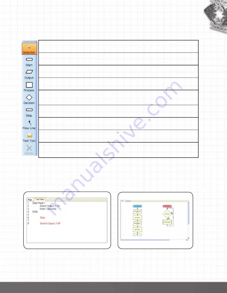
The Map and Text View
The Text View tab displays the flowchart or procedure that is in edit area in a textual format. The text
will be in red italics until the flow line is correctly set i.e. a flow line connects the symbols.
Right click in the area to alter the font size.
If you click on a line in text view it will highlight the appropriate symbol in the edit area and visa versa.
The Map tab displays the complete control program. Right click to alter the scale of view.
When a control program is run the symbols will highlight as they become active.
Click on a flowchart or procedure for it to be selected to the edit area.
back to Table of Contents


