background image


61 

18 Scrambler


18.1  Installing the Scrambler Board 

1

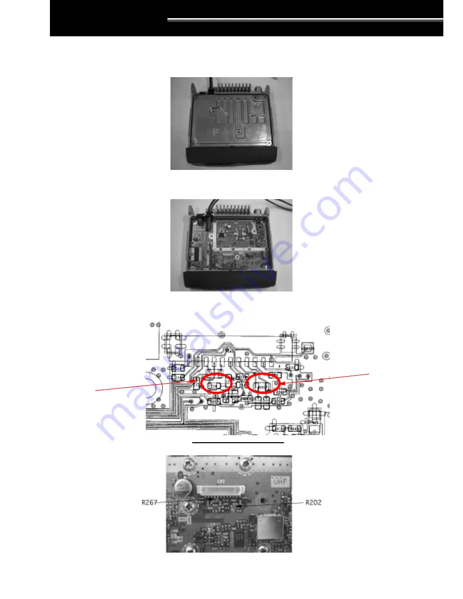
  Remove the cabinet (A01-2181-X1) and packing (G53-1544-X1), then unscrew the 8 screws (N87-2614-X6, 

M2.6) holding the cover. 


2

  Remove the cover (F10-2499-X1). 


3

  Remove resistors R267 and R202 from the TX/RX board. 


Schematic Diagram Shown 


Remove 

R267 

Remove 

R202 

Содержание TK-7100H

Страница 1: ...ocument Functions and Features of the T TK K 7 71 10 00 0H H 8 81 10 00 0H H Version Last Updated 1 01 January 20 2003 Reviewed By K Numai Date 03 05 03 Approved By D Wingo Date 03 05 03 Release Date 05 March 2003 ...

Страница 2: ...4 2 6 Talk Around 13 4 2 7 Scan 14 4 2 8 Scan Del Add 14 4 2 9 Emergency 14 4 2 10 AUX 14 4 2 11 Horn Alert 14 4 2 12 Display Character 14 4 2 13 Operator Selectable Tone 15 4 2 14 Channel Direct 15 4 2 15 Trunking Group Select 15 4 2 16 LCD Brightness 15 4 2 17 Scrambler 15 5 Scan Information 17 5 1 Overview 16 5 1 1 Requirements for Activating the Scan 16 5 1 2 Requirements for Resuming Call Dur...

Страница 3: ...2 1 2 QT DQT Decode 33 12 2 1 3 TX Frequency 34 12 2 1 4 QT DQT Encode 34 12 2 1 5 Option Signalling 35 12 2 1 6 SP Unmute 35 12 2 1 7 Busy Channel Lockout 36 12 2 1 8 Beat Shift 36 12 2 1 9 TX Power 36 12 2 1 10 Wide Narrow 36 12 2 1 11 Scan Add 37 12 2 1 12 Priority Channel 37 12 2 1 13 PTT ID 37 12 2 1 14 Scrambler 37 12 2 1 15 Scrambler Code 37 12 2 2 ID Set Mode 38 13 Internal Connector 43 13...

Страница 4: ... the Function Port of the SmarTrunk Board 60 18 Scrambler 64 18 1 Installing the Scrambler Board 61 18 2 Configuring the Function Port of the Scrambler Board 66 19 Ignition Sense 70 19 1 Using the Ignition Sense 67 19 2 Using the Ignition with the Scrambler Board 67 19 3 Using the Ignition Sense with the KDS 100 or KGP 2A 2B 70 20 Data Password 74 21 KCT 31 75 APPENDIX A 76 ...

Страница 5: ...nnel Group1 Channel1 Group2 Channel2 Group Channel Roll Over Tone Roll Over Tone 1 4 Communicating 1 4 1 Transmitting a QT DQT Code The transceiver transmits QT DQT codes when programmed in the channels of the radio and the PTT switch is depressed The receiving party s QT DQT must be the same as the transmitting party s QT DQT in order to receive tha call 1 4 2 Receiving QT DQT Codes To receive a ...

Страница 6: ...3 754 in Hexadecimal The DQT signal has polarity and can be programmed as either Normal or Inverse corresponding to a repeater or the circuit configuration of the other transceiver The Squelch Tail Eliminator when using DQT reverses the polarity from what is currently being used When the received QT DQT code matches the QT DQT code programmed in the transceiver the speaker unmutes The speaker mute...

Страница 7: ...ications The Busy Channel Lockout function prevents such interference In Systems where this function is not activated the user must monitor the Channel using the Monitor function before transmitting This function prevents the user from interfering with other users without having to first monitor the Channel status There are three methods to inhibit transmission Carrier QT DQT and DTMF You can tran...

Страница 8: ...l at the end of their transmisssion This allows unimpeded communications since the ID is not sent until the end This function is useful when you are recording communications using a PC or other recording device BOTH Both of BOT and EOT The ID is transmitted when both pressing and releasing the PTT switch The receiving party can identify the ID and the type of the ID when the PTT ID is transmitted ...

Страница 9: ...ds and the TOT Reset Timer at 3 seconds The Pre Alert tone sounds after 20 seconds of continuous transmission The transceiver stops transmitting and enters the receiving mode 10 seconds after the Pre Alert tone sounds You cannot transmit for 15 seconds from when the transceiver enters receiving mode The Time out Timer starts counting as soon as the PTT switch is pressed and continues counting even...

Страница 10: ...rd when operating the transceiver in Self Programming mode or using it as the Master in Clone Mode Entering the Password in Clone Mode or Self Programming Mode Using the Keypad Microphone KMC 32 Enter the Password via the keypad then press the key Entering the Password in Clone Mode or Self Programming Mode Using the keys of the transceiver Enter the password using MON SCN and keys then press the ...

Страница 11: ...gative terminal of the vehicle s battery is grounded to the metal of the vehicle so that the hook of the microphone enters the On Hook position when it touches a metal portion of the vehicle 3 2 11 Data TX with QT DQT This function allows you to add a QT tone or DQT code when transmitting by using the PTT function The transceiver encodes the QT DQT code programmed to the Channel when using this fu...

Страница 12: ...p 2 work as Conventional Groups even if the SmarTrunk board is installed You cannot program Trunking Groups unless you select Edit Function Port External Devices SmarTrunk 3 2 17 Mode This function allows you to select whether or not to use the Firmware Version Information and modes Clone Mode and Self Programming You can select the mode via the FPU We recommend that you disable these modes Clone ...

Страница 13: ...ignals and to adjust the volume when there is no signal You can hear background noise when the transceiver unmutes The MON icon appears when Squelch is open Press the Monitor key again to disable this function Press the Monitor key to reset the Option Signalling 4 2 5 Key Lock This function allows you to lock the transceiver s keys This prevents the user from inadvertently changing the Channel or ...

Страница 14: ...ls are skipped when the Scan is executed The Del Add status for each Channel is stored even if the transceiver is turned OFF Press the Scan Del Add key during Scan to execute the Temporary Delete function The Temporary Delete function is used to delete Channels on which Scan pauses Exit Scan or turn the transceiver OFF to reset the temporarily deleted Channels to their default state 4 2 9 Emergenc...

Страница 15: ...is function allows you to switch the Group Code of the SmarTrunk Board ST865KW4 Press the Trunking Group Select key to increase the Group Code 4 2 16 LCD Brightness This function allows you to adjust the brightness of the display The brightness toggles between High and Low every time the LCD Brightness key is pressed 4 2 17 Scrambler You can use this function when a Voice Scrambler is installed Th...

Страница 16: ...o a group that does not meet the requirements for resuming Scan In this case Scan does not resume The transceiver transmits using the Revert Channel when pressing the PTT switch when Scan has not resumed The transceiver returns to the previous Channel after the Dwell Time expires Scan does not resume 5 1 3 Operation Manual Change of Group Channel During Scan The following operations occur when cha...

Страница 17: ...the Priority Channel when a carrier does not match the programmed QT DQT during Priority Scan Other stations may be using the same frequency as the Priority Channel therefore Look back Time B must be longer than Look Back Time A as the transceiver may not receive a call from the Priority Channel immediately The Priority Channel stand by time becomes longer as the transceiver checks the QT DQT when...

Страница 18: ...his function The Group Add function is disabled when the Single Scan is selected This function scans only the selected Group 5 2 7 2 Multi Scan This function scans all in the Groups added to the Scan List and all the Channels in those groups that are added to the Scan List using the FPU or by pressing the Scan Del key You must select Multi to activate this function The requirements for operating S...

Страница 19: ...Tones The transceiver automatically transmits DTMF using PTT ID Auto Dial Store Send and Redial This function ensures the reception of the DTMF Tone 6 2 4 No of DTMF Keys This function allows you to select whether or not to use the A B C and D keys of the Keypad Microphone KMC 32 You can select 12 keys A B C and D are not available or 16 keys A B C and D are available You can use 12 keys when acce...

Страница 20: ...t when Manual Dial is disabled The Store Send box is greyed out when Keypad Auto PTT is enabled and vice versa 6 2 9 Autodial This function allows you to automatically transmit the DTMF Code Autodial Memory You can program up to 9 Autodial Memories 6 2 9 1 Transmitting from the Autodial Memory 1 Press the key 2 Enter the Autodial Memory number you want to transmit 1 9 The Error tone sounds when th...

Страница 21: ... when transmitting a DTMF Code using PTT ID 6 2 11 Store Send This function allows you to automatically transmit the stored DTMF Code using the keypad 1 Enter the DTMF Code via the keypad In this case keys 1 2 and 3 are pressed 2 Press the PTT switch to transmit the DTMF Code 3 Press the key to enter Autodial mode when using the Autodial and Store Send function at the same time 4 Press the key aga...

Страница 22: ...The Status Code appears when receiving an ID Intermediate Code Example ID Code 1234 Intermediate Code Status Code 5678 Receiving 1234 5678 1234 is the ID Code Intermediate Code The transceiver transmits the Transpond signal the CALL icon appears and the Call Alert Tone sounds The transceiver recognizes 5678 as the Status code Receiving 1234 The transceiver transponds the CALL icon appears and the ...

Страница 23: ...Timer expires after the user ends communication You may disable this function Match status is reset when activating the Monitor or Scan function or when changing the Channel Default 10 s Range OFF 0 15 s 6 3 7 Call Alert The Call Alert Tone sounds when receiving a call using DTMF There are three types of tones You may also disable the tone Normal The Call Alert Tone sounds only once Continuous The...

Страница 24: ...t matches the code programmed in the transceiver Pulse The Horn Alert Port toggles between Low and High every 500 ms three times 500 ms 500 ms 500 ms 500 ms 500 ms Continuous The Horn Alert Port remains Low for the time programmed in the Horn Alert Time Horn Alert Time 6 3 11 Horn Alert Time The Horn Alert Time is the duration the Horn Alert Port remains Low after receiving a matching DTMF ID Code...

Страница 25: ...eal time The PTT ID transmitted from the communication port is used to administrate the communications log 7 2 Description of Function 7 2 1 Fleet ID You must program a FleetSync ID for each transceiver in order to use FleetSync The FleetSync ID consists of a 3 digit Fleet number and a 4 digit ID number You can program the Fleet number between 100 and 349 and the ID number between 1000 and 4999 7 ...

Страница 26: ...The transceiver enters normal operation the next time it is turned ON However you cannot switch the transceiver OFF when the Emergency Power Switch is programmed even though the display blacks out Pressing and holding the Emergency key for more than 10 seconds When the Emergency Manual Reset function is programmed you can exit Emergency Mode by pressing and holding the Emergency key for more than ...

Страница 27: ...up to 16 digits using 0 9 A D and The transceiver exits Emergency Mode when it receives the Emergency Reset Code and returns to normal opearation 8 1 8 Emergency FleetSync No ID You can program the Emergency FleetSync No ID when MSK is selected as the Emergency Type The dispatch radio s ID should be programmed as the emergency ID so that the emergency is directed to a radio that always has an oper...

Страница 28: ... is programmed 8 1 13 Emergency Cycle This function allows you to program the number of times that the transceiver switches between transmission and receiption The transceiver switches between automatic transmission and reception for the programmed number of times It enters normal operation when it finishes the cycle The transceiver continues to switch between automatic transmission and receiption...

Страница 29: ...MF Ack Code from the dispatcher Note The display does not change until the transceiver enters the Emergency Mode when the Secret Emergency function is enabled and the Emergency Recognition function is disabled Note You cannot disable the Emergency Recognition function when the Secret Emergency function is disabled 8 1 17 Emergency Manual Reset This function allows you to select whether or not to e...

Страница 30: ...n the OST table You can program up to 8 characters for the OST Name using the following characters space 0 1 2 3 4 5 6 7 8 9 _ A B C D E F G H I J K L M N O P Q R S T U V W X Y Z TONE 1 TONE 16 appears when an OST Name is not programmed 9 2 2 QT DQT Decode This function allows you to program the QT DQT for reception You can program the QT DQT Decode using the FPU table QT 67 0 254 1 Hz Select from...

Страница 31: ...ver enters the Firmware Version Information Mode when turning it ON while pressing the key The version information is displayed while the key remains pressed Release the key to return to normal operation Firmware Version Information Mode display Note The Firmware Version is no longer displayed when the transceiver exits the Firmware Version Information Mode ...

Страница 32: ...ission ends The Clone Slave transceiver automatically activates with the new data ERROR appears when the cloning process fails 11 2 3 Cloning Additional Transceivers END appears when the transceiver ends cloning Press the MON key on the Clone Master transceiver to enter the Clone Mode again Press the MON key again to transmit data Repeat this operation to clone the configuration data to several tr...

Страница 33: ...he Channel to the Group Press the CH DOWN key to change the Group number Press the SCN key after selecting the Group and Channel Following are the operations for configuring the Channel Press the key to select the item Press the key to store the change You can move to other items after the change is stored Press the MON key to program the Group Channel The function of the key varies corresponding ...

Страница 34: ...ction allows you to program the transmit frequency The current frequency appears after the T Press the key to change the frequency step Press and hold the key for more than 1 second on a programmed Channel to delete the Channel Press and hold the key for more than 1 second on a Channel that is not programmed to display the default frequency 12 2 1 4 QT DQT Encode This function allows you to progra...

Страница 35: ...MF Decode The following display appears when using DTMF Decode Note You cannot use the key for this configuration 12 2 1 6 SP Unmute This function allows you to program the conditions for unmuting the speaker The transceiver unmutes the receiver when receiving the carrier You can select Carrier only when the QT DQT Decode is set to None The transceiver unmutes the receiver when the received QT DQT...

Страница 36: ...sceiver does not transmit when the received QT DQT code does not match with the QT DQT code programmed in the Channel The transceiver transmits when the DTMF matches Note You cannot use the key for this configuration 12 2 1 8 Beat Shift This function allows you to enable disable the Beat Shift The CPU clock frequency does not shift The CPU clock frequency shifts Note You cannot use the key for thi...

Страница 37: ...he above display appears when the selected Channel is not programmed as the Priority Channel Note You cannot use the key for this configuration 12 2 1 13 PTT ID This function allows you to select whether or not to use the PTT ID The transceiver does not use the PTT ID The transceiver uses BOT The transceiver uses EOT The transceiver uses both BOT and EOT Note You cannot use the key for this config...

Страница 38: ...the display to enter the ID Set Mode In this mode you can program the DTMF ID for the DTMF Decode using the Keypad Microphone KMC 32 The current DTMF ID appears 000 in this example when the transceiver enters the ID Set Mode Press the MON key or the key to return to the main display SELF appears without storing the data Press the SCN key to store the changes in the configuration data and return to...

Страница 39: ...6 I O Programmable 11 FNC7 I O Programmable 12 FNC8 I O Programmable CN4 No Name I O Function Impedance Coupling Specifications 1 GND Ground 2 NC 3 NC 4 NC 5 FNC2 I O Programmable 6 NC 7 NC 8 FNC3 I O Programmable 9 FNC1 I O Programmable 10 NC 11 5C 5 V DC power supply 5 V DC Max 50 mA 12 NC 13 DATAI I External transmit signal input 120 k AC 1 kHz 500 mVrms Input STD Dev Before pre emphasis 14 DET...

Страница 40: ...CN2 ports FNC1 FNC8 Function Port using the FPU You can program the Function Port in Edit Function Port using the FPU Port 1 Port 8 in the FPU corresponds to FNC1 FCN 8 of CN2 13 2 1 External Devices You can assign a function for each port With this function Port 1 Port 8 are customized when selecting devices to install None You can program Port 1 Port 8 KDS 100 You can program the KDS 100 when co...

Страница 41: ... Data Bit Length 8 bits Order of Output Bit Begin from LSB Baud Rate 9600bps 13 2 2 2 Communication Format The following list is for the communications format STX Command 2nd Data ETX STX STX stands for the Start of TX communication starts from STX The STX value is always 02 Hex Command You can enter the command using the ASCII Code 2nd Data This is the data that follows the Command its definition...

Страница 42: ...Radio to PC The transceiver transmits the TX End command when it enters the receiving mode STX C ASCII ETX PC to Radio The transceiver ends the transmission when it receives the TX End command from the PC STX C ASCII ETX 13 2 2 7 DTMF Radio to PC The transceiver transmits the DTMF command when it decodes the DTMF signal STX I ASCII DTMF Code ASCII ETX The DTMF Code consists of a maximum of 16 digi...

Страница 43: ...ey Name Key Data Keypad 0 20 Keypad 1 21 Keypad 2 22 Keypad 3 23 Keypad 4 24 Keypad 5 25 Keypad 6 26 Keypad 7 27 Keypad 8 28 Keypad 9 29 Keypad A 2A Keypad B 2B Keypad C 2C Keypad D 2D Keypad 2E Keypad 2F PC to Radio None 13 2 2 11 Audio Mute Radio to PC None PC to Radio Muting the transceiver STX T ASCII 1 ASCII ETX Disabling the Audio Mute function STX T ASCII 0 ASCII ETX 13 2 3 Hook Input You m...

Страница 44: ...KDS 100 and KGP 2A 2B Example The KDS 100 uses the FleetSync individual call function With this function the KDS 100 continues transmitting data at Low level through this terminal until it receives a call from the transceiver The transceiver mutes even if it finds a carrier or QT DQT 13 2 9 Mic Mute Input You may assign this input terminal to one of Port 1 Port 8 The transceiver mutes the micropho...

Страница 45: ... 2 17 Horn Control Output You may assign this output terminal to one of Port 1 Port 8 You may use this terminal for the Horn Alert function and the Emergency function The Horn Control logic changes when the transceiver receives the DTMF or enters the 2nd Emergency Mode See APPENDIX A in detail 13 2 18 Light Control Output You may assign this output terminal to one of Port 1 Port 8 You may use this...

Страница 46: ...for details The KCT 39 has this terminal However this terminal is not used in the KDS 100 and KGP 2A 2B Note This terminal does not work with the Power until R71 on the board is removed Without removing R71 90 of the battery is output when applying the 39k as the internal resistance is approximately 4 7k 13 3 4 DATAI CN3 Pin2 This is the input terminal for external signalling devices The signal is...

Страница 47: ...Hz 3 kHz before it passes through the De Emphasis circuit Refer to Section 18 Scrambler for details 13 3 10 ALTI CN3 Pin8 This terminal allows you to input an external Alert Tone You may use this terminal for the SmarTrunk Board 13 3 11 RXAFI CN3 Pin9 This input terminal allows you to input the receive audio signal to the Scrambler You must remove R267 and connect it to the RXAFO terminal You must...

Страница 48: ...nnector for the functions of each pin No Color Internal Connector Name 1 Red CN2 1 SB 2 Pink CN3 1 IGN 3 Black CN2 3 GND 4 Brown CN3 3 DETO 5 Orange CN3 2 DATAI 6 Yellow CN2 8 FNC4 7 Green CN2 7 FNC3 8 Blue CN2 9 FNC5 9 Purple CN2 12 FNC8 10 Grey CN2 10 FNC6 11 White CN2 11 FNC7 12 NC NC 13 NC NC 14 Light blue CN2 6 FNC2 15 Pale blue CN2 5 FNC1 Looking at the connector from the direction indicated...

Страница 49: ...14 KCT 39 49 Connector connection 1 Remove the cabinet A01 2181 X1 and 8 screws N87 2614 X6 M2 6 2 Remove the cover F10 2499 X1 3 The following figure shows the layout of the speaker cable ...

Страница 50: ...he DC cord E30 3339 X5 from the chassis 5 Remove the cushion G13 1468 X4 from the chassis below the DC code 6 Install a Stick cushion G13 1961 X8 onto the chassis 7 Install another Stick cushion G13 1960 X8 onto the DC cord ...

Страница 51: ...14 KCT 39 51 8 Insert the cable into the TX RX PCB 9 Position the KCT 39 as shown in the following figure ...

Страница 52: ...14 KCT 39 52 10 Connect Terminal A of the KCT 39 to CN 2 and Terminal B to CN 3 11 Position the speaker cable T07 1082 X5 below the vinyl wires 12 The following displays the KCT 39 layout CN3 CN2 ...

Страница 53: ...14 KCT 39 53 13 Close the cover and mount the cabinet ...

Страница 54: ...14 KCT 39 54 ...

Страница 55: ...S 100 All necessary parameters for the KDS 100 are automatically configured 6 Select Program Write to Radio in the FPU Menu 7 The configuration data is sent to the transceiver 8 The KDS 100 automatically activates when the transceiver is turned ON Note You must use KPG 71D to program the KDS 100 Note Select Edit Optional Features Radio in the FPU Menu to program the logic of each port SQ Squelch d...

Страница 56: ...S 100 Select KGP 2A 2B All necessary parameters for KGP 2A 2B setup are automatically configured 6 Select Program Write to Radio in the FPU Menu 7 The configuration data is sent to the transceiver 8 The KGP 2A 2B automatically activates when the transceiver is turned ON Note You must use KPG 73D to program the KGP 2A 2B Note Select Edit Hardware Setup in the FPU Menu to program the logic of each p...

Страница 57: ...inet A01 2181 X1 and packing G53 1544 X1 then unscrew the 8 screws N87 2614 X6 M2 6 holding the cover 2 Remove the cover F10 2499 X1 3 Remove the SmarTrunk board ST 865KW4 from its package SmarTrunk accessories Note As of October 2002 cushion D has not yet been included ...

Страница 58: ...Install cushions C 20 mm x 20 mm x 1 mm and B 10 mm x 10 mm x 2 mm onto the back of the SmarTrunk board 5 Install cushion D 12 mm x 9 mm x 6 mm and the insulation sheet 22 mm x 22 mm on the surface of the SmarTrunk board ...

Страница 59: ...following figures show the SmarTrunk after completing the installation 7 Connect the CN4 connector and the SmarTrunk board to the surface of the TX RX printed board 8 Close the cover install the packing and fasten the screws ...

Страница 60: ...lect SmarTrunk All necessary parameters for the SmarTrunk are automatically configured 4 The configuration data is sent to the transceiver 5 The SmarTrunk board automatically activates when the transceiver is turned ON Note Select Edit SmarTrunk in the FPU menu to change the SmarTrunk configuration Write the data to the SmarTrunk board in the Program Write Data to Trunking Board display Note Read ...

Страница 61: ...d 1 Remove the cabinet A01 2181 X1 and packing G53 1544 X1 then unscrew the 8 screws N87 2614 X6 M2 6 holding the cover 2 Remove the cover F10 2499 X1 3 Remove resistors R267 and R202 from the TX RX board Schematic Diagram Shown Remove R267 Remove R202 ...

Страница 62: ...l Refer to the SC20 460 Installation Manual For RX For TX Change C1 to 1000 pF Change R2 to 15 kΩ Change R1 to 39 kΩ Change R4 to 15 kΩ Change R3 to 330 kΩ 6 You can change the Scrambler configuration using the TRANSCRYPT software and TR30 3060 3061 The parameters change when adjusting TX RX and De Emphasis Miscellaneous Parameter 1 Bit Number 4 TX De Emphasis Set to default 0 Miscellaneous Parame...

Страница 63: ... connector and E37 1081 X5 12 pin lead wire with connector can be supplied as service parts 8 Solder E37 1080 X5 11 pin lead wire with connector and E37 1081 X5 12 pin lead wire with connector onto the Scrambler board Connect the wires as shown in the following figures 12 pin Lead Wire with Connector E37 1081 X8 11 pin with Lead Wire with Connector E37 1080 X8 ...

Страница 64: ... 11 B 9 12 B 4 9 Install cushion G13 1963 X4 33 mm x 15 mm x 5 mm on the surface of the Scrambler board and cushion G13 1964 X4 38 mm x 25 mm x 1 mm on the back of the board Cushion G13 1963 XX Cushion G13 1964 XX Mount cushion G13 1963 XX onto the top of the SC20 460 Mount cushion G13 1964 XX onto the back to the SC20 460 Note G13 1963 X4 and G13 1964 X4 can be ordered as service parts ...

Страница 65: ...o the TX RX board 11 Following is the layout of the soldered wires Note The speaker cable passes under the Scrambler wire Note Do not sandwich the Scrambler wire between the cover and the PCB 12 Close the cover install the packing and fasten the screws ...

Страница 66: ... for operating the Scrambler board Select Scrambler All necessary parameters for the Scrambler are automatically configured 3 Select Program Write to Radio in the FPU Menu 4 The configuration data is sent to the transceiver Note You must enable disable the Scrambler function and program the Scrambler code for each Channel Note You can change the Scrambler configuration using the Scrambler key ...

Страница 67: ...d of the KCT 39 to the Ignition of the car 5 Connect the second pin pink of the KCT 39 to the Ignition line of the car 19 2 Using the Ignition with the Scrambler Board The Scrambler board uses connector CN 3 for the Ignition Sense terminal Therefore you cannot connect the KCT 39 However you can use the Ignition Sense and the Scrambler Board at the same time by soldering a cable onto the Ignition S...

Страница 68: ...wire between the top panel and the PCB The following figures are example of wiring 2m m Tie a knot in the cable here Cable Tie Type Length 100 m m 3 9 W idth 2 5m m 0 10 Max Bundle 18 m m Ignition Cable Type UL1007 AW G 26 or AW G 28 Internal ...

Страница 69: ...lthough the Ignition Sense has dust proof capability this characteristic may not be performed when connecting a cable available on the market to the Ignition Sense Note Remove resistor R71 on the A side of the TX RX PCB when connecting a cable other than the KCT 39 ...

Страница 70: ...Low There are three ways to use the Ignition Sense with the KDS 100 or KGP 2A 2B 1 Solder the cable onto the Ignition Sense pad Solder a normal cable onto the pad as explained in the preceding section 2 Modify the KCT 39 Cut the second pin pink of the KCT 39 so as not to connect the KDS 100 to the Ignition Line of the vehicle 3 Program the Function Port using the FPU Select None in the External de...

Страница 71: ...appears when the transceiver enters the Self Programming Mode The following keys represent the correspondng numbers MON 1 SCN 2 3 4 CH DOWN Password confirmation The transceiver enters the Self Programming Mode when the entered password matches the programmed password SELF appears SELFLOCK appears when the entered password is wrong Clone Mode CLN LOCK appears when the transceiver enters the Clone ...

Страница 72: ...ow TxD Cut the cable as shown in the following figure Solder the line to re connect the line Change the position of pins Use pins 1 3 5 and 6 from the left Connect the connector to CN 2 of the TK 7100H 8100H from the left 1st pin side The PC controls the transceiver using the RxD TxD programmed to the Function Port Note Connect the 8 Pin connector to CN 2 2nd Pin connector Do not connect the conne...

Страница 73: ...vate the relay The transistor is biased on by the function port output with the V supplying the current necessary to activate the relay The transistor rating will determine the value of the series resistor used between the function port output and the base of the transistor Reverse Bias diode In the example shown the transistor switches to provide a path for current flow through the coil When the ...

Страница 74: ...le 31 Emergency Display 31 Emergency FleetSync No ID 30 Emergency Group Channel 29 Emergency Manual Reset 32 Emergency Mic 31 Emergency Power Switch 31 Emergency Recognition 32 Emergency Reset Code 30 Emergency Type 29 EOT End of TX 8 External Devices 44 F Firmware Version Information 12 Firmware Version Information Mode 5 34 First Digit Delay 20 First Digit Time 20 Fleet ID 28 FleetSync Baud Rate...

Страница 75: ...equirements for Resuming Call During Scan 17 Reset Output 50 Revert Channel 19 RX Frequency 36 S Scan 14 Scan Add 7 40 Scan Del Add 14 Scrambler 16 41 44 64 Scrambler Output 50 Scrambler Code 8 41 Scrambler Code Output 50 Secret Emergency 31 Self Programming 12 Self Programming Mode 5 36 Single Scan 19 SmarTrunk 44 60 SP Unmute 7 39 Squelch Level 9 Starting the Cloning Process 35 Store Send 23 Sto...

Отзывы: