13 Internal Connector
41
You can easily identify the External Devices
configuration of each device.
13.2.2 RxD (Input)/TxD (Output)
You can program RxD (Input) for Port 2 and TxD
(Output) for Port 1.
You must use the RxD/TxD terminal at the same
time.
The PC controls the transceiver when connecting the
RxD/TxD terminal to the RS-232C port using the
Interface Cable (KCT-31). However, you must
change the position of the pin. Refer to Section “21
KCT-31” for details.
13.2.2.1 Protocol
The following descriptions are of the RxD/TxD
protocol format:
• Send Format:
Full Duplex
• Sync. Format:
Asynchronous
• Parity
Bit:
none
• Start Bit:
1 bit
• Stop Bit:
2 bits
• Data Bit Length:
8 bits
• Order of Output Bit: Begin from LSB
• Baud Rate:
9600bps
13.2.2.2 Communication
Format
The following list is for the communications format:
STX + C 2nd Data + ETX
STX
STX stands for the Start of TX; communication
starts from STX. The STX value is always 02
(Hex).
Command
You can enter the command using the ASCII
Code.
2nd Data
This is the data that follows the Command; its
definition and data length vary corresponding to
the Command.
Some commands do not have the 2nd Data.
ETX
ETX stands for the End of TX; the communication
ends with ETX. The ETX value is always 03
(Hex).
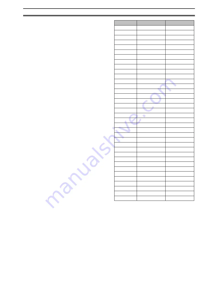
Command
Action
Direction
0
1
2
COR
Radio to PC
3
4
TOR
Radio to PC
5
6
7
8
9
A TX
Start Both
B
C TX
End Both
D
E
F
G
H
I DTMF Both
J
K Volume Both
L
Channel
PC to Radio
M
Key Status
Radio to PC
N
O
P
Q
R
S
T
Audio Mute
Radio to PC
U
V
W
X
Y
Z


