


- 191 -
6. Description of Parameters
- 191 -
6
Value
Function
Description
12
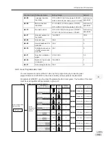
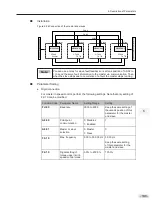
Multi-reference terminal 1
16 speeds or 16 other references can be implemented
through combinations of 16 states of these four terminals.
13
Multi-reference terminal 2
14
Multi-reference terminal 3
15
Multi-reference terminal 4
16
Terminal 1 for
acceleration/deceleration
time selection
Totally four groups of acceleration/deceleration time can be
selected through combinations of four states of these two
terminals.
17
Terminal 2 for
acceleration/deceleration
time selection
18
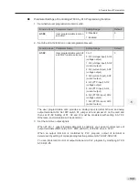
Frequency reference
setting channel
switchover
The terminal set for this function is used to perform
switchover between two frequency reference setting channels
according to setting in F0-07.
19
UP and DOWN setting
clear (terminal, operation
panel)
If the frequency source is digital setting, the terminal set for
this function is used to clear the modification by using the
UP/DOWN function or the increment/decrement key on the
operation panel, restoring the frequency reference to the
value of F0-08.
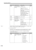
20
Command source
switchover 1
If command source is terminal control (F0-02 = 1), this
terminal is used to perform switchover between terminal
control and operation panel control.
If command source is communication control (F0-02 =
2), this terminal is used to perform switchover between
communication control and operation panel control.
21
Acceleration/Deceleration
prohibited
This function ensures the AC drive to maintain current
frequency output without being affected by external signals
(except STOP command).
22
PID disabled
This function disables the PID function. The AC drive
maintains current frequency output without supporting PID
adjustment of frequency reference.
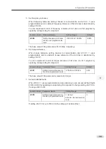
23
PLC state reset
When the simple PLC function is enabled again after it was
disabled in execution process, this function restores original
state of simple PLC for the AC drive
24
Wobble disabled
When terminal set for this function becomes on, the wobble
function becomes disabled and the drive outputs center
frequency.
25
Counter input
Terminal set for this function is used to count pulses.
26
Counter reset
Terminal set for this function is used to clear counter.
27
Length signal pulses
count
Terminal set for this function is used to count pulses of the
length signal.
28
Length reset
The terminal set for this function is used to clear length.
29
Torque control prohibited
When the terminal set for this function becomes on, torque
control is disabled and the AC drive enters speed control.
30
Pulse input as frequency
reference (valid only for
DI5)
DI5 is used for pulse input as frequency reference.
31
Reserved
-
32
Immediate DC injection
braking
Once the terminal set for this function becomes on, the AC
drive directly switches over to DC injection braking state.
Содержание GT600-4T132G
Страница 1: ...GT600 AC Drive...
Страница 5: ......
Страница 86: ...5 Quick Setup 5 1 Get Familiar With Operating Panel 86 5 2 Setup Flowchart 87...
Страница 87: ......
Страница 100: ...5 Quick Setup 98 5...
Страница 280: ...8 Peripherals and Options 278 8...
Страница 306: ...12 303 11...
Страница 362: ......