Page 16
ENGLISH
Jandy
®
Pro Series, Hi-E2
®
and Hi-E2R Gas-Fired Heater
|
Installation & Operation Manual
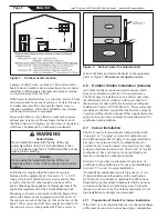
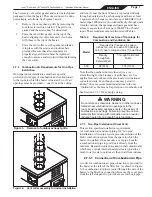
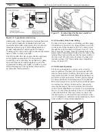
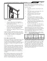
Figure 21. Piping to heater.
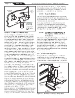
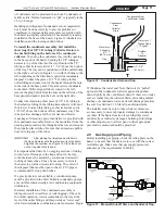
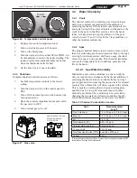
Figure 22. Pressure relief valve installation.
Water In
Out
Method For Installing
Any Threaded Pipe
For Nonthreaded Pipe
or Tube, Discard
Plastic Sleeve
Use
Plastic
Sleeve
pool surface a leak can result in large scale water loss or
flooding. Zodiac cannot be responsible for such water loss
or flooding or the damage caused by it.
Do not install a shutoff valve or any kind of variable
restriction in the water piping between the heater outlet
and the pool/spa.
Pool systems with water flow rates higher than 100 GPM
require an adjustable external bypass at the heater. See the
section on start-up and adjustment for this information.
2.11.3 Connections at Heater
The Hi-E
2
has a universal water header and flange design.
With this feature, a variety of piping materials and sizes
can be used at the heater. 1-1/2" PVC or 2" copper pipe
can be connected directly to the heater using the rubber
“donut” gaskets provided with the heater. 2" PVC or metal
pipe can be threaded directly to the flanges and 1-1/2"
schedule 40 metal pipe can be used with the rubber donut
gaskets. See Figure 21.
2.11.4 Pressure Relief Valve and
Temperature Relief Valve
A pressure relief valve (PRV) is recommended in all
installations, and is mandatory in any installation in which
the water flow can be restricted between the heater outlet
and the pool/spa. A pressure relief valve may also be
required by local codes and a pressure relief valve must
be provided in Canada. Be sure to check any applicable
installation codes in your area to determine whether a
pressure relief valve is required.
A pressure relief valve is not supplied with the Hi-E
2.
All
equipment installations need to be in accordance with the
manufacturers instructions.
To install a pressure relief valve:
1.
Remove the 3/4" brass plug from the top of the
inlet/outlet header, see Figure 22.
2.
Install the pressure relief valve in the opening.
Make sure to get a sung fit. Do not overtighten.
3.
Provide a short length of brass or stainless steel
pipe as necessary to position the valve above the
sheet metal cover.
5.
The final orientation of the pressure relief valve
should be vertically aligned with the discharge
opening facing away from the heater.
6.
Install a discharge pipe from the pressure relief
valve discharge opening to a safe area. This is a
precaution to prevent the possibility of personal
injury or property damage in the event scalding
water is discharged from the pressure relief valve.
7.
Install the discharge pipe so that there is no
trapped or standing water in the piping. Discharge
piping must be facing down, terminating with a
threadless nipple, no less than 6” from floor.
The heater must be protected from back-siphoning of
water, which can result in dry starts. If there is any chance
of back-siphoning, provide a check valve between the
pool and the filter pump inlet.
Arrangement of pool system components other than as
illustrated in these diagrams can affect the operation of
the heater’s water pressure switch. Location of the heater
above or below the pool water surface can also affect
operation of the switch. In general, the pressure switch
can be adjusted to accommodate this effect if the heater
water connections are no more than six feet below the
pool water surface and no more than 15 feet above it. See
instructions for pressure switch adjustment in the heater
start-up section of this manual for more information about
this. Note that when pool equipment is located below the
Содержание HI-E2
Страница 2: ......
Страница 37: ...Page 37 ENGLISH Jandy Pro Series Hi E2 and Hi E2R Gas Fired Heater Installation Operation Manual NOTES...
Страница 38: ...Page 38 ENGLISH Jandy Pro Series Hi E2 and Hi E2R Gas Fired Heater Installation Operation Manual NOTES...
Страница 39: ...Page 39 ENGLISH Jandy Pro Series Hi E2 and Hi E2R Gas Fired Heater Installation Operation Manual NOTES...


