


Page 27
ENGLISH
Jandy
®
Pro Series, Hi-E2
®
and Hi-E2R Gas-Fired Heater
|
Installation & Operation Manual
F
Hi-E2
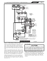
Figure 32. Wiring diagram with test points.
4.5 Electrical Trouble Shooting
WARNING
ELECTRICAL SHOCK HAZARD.
This heater contains
wiring that carries high voltage. Contact with these
wires may result in severe injury or death.
CAUTION
Label all wires prior to disconnection when servicing
controls. Wiring errors can cause improper and
dangerous operation. Verify proper operation after
servicing.
This section describes procedures for checking the electri
-
cal power and control components of the heater one at a
time and in the order they appear in the control circuit.
These procedures require a Volt-Ohm meter with 0-150
VAC range, and 0-1000 Ohm resistance range. Figure 32
shows the power and control circuits, and where to take
measurements. Location numbers in circles have been
added, and will be referenced in the following sections.
As stated at the beginning of this manual, some of these
procedures are hazardous. Only a qualified service
technician should service the heater.
4.5.1 115V Electrical Power Supply
The electrical components of the Hi-E
2
pool heater are
designed to operate with supply voltage ranging from
103V to 126V at 60 Hz. Measure supply voltage at the
“hot” and “neutral” wirenut connections in the heater
electrical junction box (identified as points A and B on
the wiring diagram). If no voltage is present, correct
this external to the heater. Circuit breakers, time clock
settings or similar devices may be the problem. Voltage
outside of the above range may be due to poor wiring,
poor connections, other loads such as air conditioning
compressors or to an electric utility company problem.
Arrange for correction of the voltage as appropriate.
4.5.2 Control Circuit Trouble Shooting
The heater controls are in a 24V 60 Hz circuit
with operating and safety controls basically
arranged in a series circuit. Trouble shooting is
done by probing for voltage at various points
in the circuit to determine which component
is preventing operation. Check points are
indicated on Figure 32. The recommended
procedure steps through the circuit in a
sequential way, but verifying voltage at any
of the numbered points confirms that all prior
components are OK. Experienced technicians
may be able to shorten the process by going
directly to one of the intermediate test points.
4.5.2.1 Transformer
A
ttach one lead of the voltmeter to the
transformer terminal with a yellow wire
attached to it, which is point 11 on Figure 32.
(This lead can be left in place for most of the
testing.) Touch the free lead of the meter to the
transformer terminal with a red wire, point 1.
The meter should show 20-28 volts. If there is
no voltage, replace the
transformer.
4.5.2.2 Fuse
Leaving the “common” voltmeter lead in place
at point 11, touch the free probe to point 2.
This is the terminal block screw attached to
the red wire from the in-line fuse, and absence
of voltage indicates a defective fuse. If there
is no voltage, inspect the rest of the wiring to
be sure that there is no “short” such as contact
of a terminal with the heater chassis or another
terminal. Correct any such condition and
replace the fuse.
Содержание HI-E2
Страница 2: ......
Страница 37: ...Page 37 ENGLISH Jandy Pro Series Hi E2 and Hi E2R Gas Fired Heater Installation Operation Manual NOTES...
Страница 38: ...Page 38 ENGLISH Jandy Pro Series Hi E2 and Hi E2R Gas Fired Heater Installation Operation Manual NOTES...
Страница 39: ...Page 39 ENGLISH Jandy Pro Series Hi E2 and Hi E2R Gas Fired Heater Installation Operation Manual NOTES...


