


Page 15
ENGLISH
Jandy
®
Pro Series, Hi-E2
®
and Hi-E2R Gas-Fired Heater
|
Installation & Operation Manual
AQUAPURE
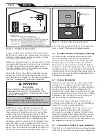
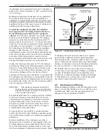
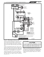
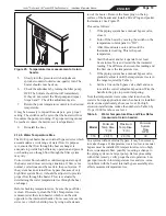
MANUAL BY-PASS DETAIL
MANUAL BY-PASS IS USED
WHEN FILTRATION RATE
EXCEEDS 125 GPM
Figure 20. Typical water piping.
2.11 Water Piping
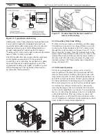
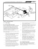
2.11.1 Reversal of Water Connections
The Hi-E
2
is shipped with water connections on the right
side, but it can be modified in the field to provide left-
side water connections. This is done by removing the
water headers and re-installing them opposite to their
original location. Some of the heater wiring and control
components must be relocated, so this change must be
done only by a trained service technician.
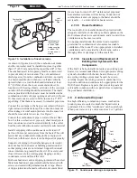
Water connection reversal is illustrated in Figures 18 and
19. Proceed as follows:
1.
Remove the vent exhaust grille by removing the
four (4) screws which retain it. Retain these and
all other parts for later reassembly.
2.
Remove the top cover by removing the screws
around the edges, under the overhang.
3.
Remove the header covers. Note that the return
header cover is retained by wing nut fasteners
inside the heater
.
4.
Disconnect the pressure switch wires and remove
the pressure switch tube from the inlet/outlet
header by unscrewing the brass fitting.
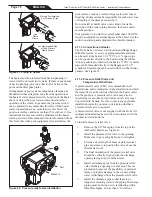
5.
Remove the temperature control sensor by
removing the retainer bracket and its cap screws.
6.
Disconnect the limit switch wires from the limit
switches. The limit switches and the short wire
between them may be left in place.
7.
Remove both headers by unscrewing eight (8) cap
screws retaining each header.
8.
Install the inlet/outlet header on the left side of the
heater and the return header on the right. Position
gaskets carefully to avoid water leaks.
9.
Re-route the limit switch wires in front of the
venturi tailpipe and attach them to the limit
switches.
10. Re-route the temperature sensor wires in front of
the venturi tailpipe and insert the sensor into the
header. When the inlet/outlet header is on the left
side, the sensor opening is at the rear. Re-install
the retainer bracket and screw.
11. Re-install the pressure switch tube and fitting.
Relocate fitting.
12. Adjust wiring and pressure switch tube routing
so that they don't rest on sharp edges or on
the hot surfaces of the combustion chamber.
The combustion chamber is the portion of the
assembly just above the heat headers.
13. Re-assemble all other components and fasteners.
2.11.2 Pool/Spa Piping Systems
Figure 20 illustrates typical piping for pool equipment
in pool/spa combination pools. With its Flex-Temp
temperature control, the Hi-E
2
is particularly suitable for
this type of pool installation.
Содержание HI-E2
Страница 2: ......
Страница 37: ...Page 37 ENGLISH Jandy Pro Series Hi E2 and Hi E2R Gas Fired Heater Installation Operation Manual NOTES...
Страница 38: ...Page 38 ENGLISH Jandy Pro Series Hi E2 and Hi E2R Gas Fired Heater Installation Operation Manual NOTES...
Страница 39: ...Page 39 ENGLISH Jandy Pro Series Hi E2 and Hi E2R Gas Fired Heater Installation Operation Manual NOTES...


