Page 10
ENGLISH
Jandy
®
Pro Series, Hi-E2
®
and Hi-E2R Gas-Fired Heater
|
Installation & Operation Manual
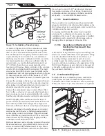
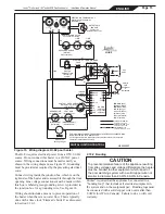
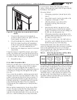
Figure 10. Installation of insect screens.
Install special
insect screen
at end of pipe
inside coupling
or elbow. Cut
to size as nec-
essary.
Combustion
Air Pipe
Elbow
Vent
Exhaust
Pipe
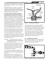
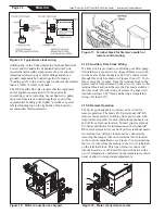
Figure 11. Condensate drainage components.
To
Disposal
Vent
Drain
Collector
Drain
Trap/
Neutralizer
Blower
Drain
As shown in Figures 8 and 9, the combustion air intake
and the vent outlet must be installed no closer together
than 18" (45.7cm) and no farther apart than 60" (1.5m).
The combustion air inlet opening must face downward
to prevent entry of rain or snow. The vent outlet must
discharge away from the combustion air inlet - normally
in a horizontal direction when on a wall and vertically
upward when on a roof. Both should terminate at least
12" (30.5cm) above the snow accumulation level. In
locations with freezing climate, extension of the vent pipe
outside of the building should be minimized. The insect
screens provided with the heater must be installed at the
combustion air and vent pipe openings as shown in Figure
10. Insect screens are sized to fit the inside of a 5" PVC
pipe fitting. Trim them as necessary for smaller pipe sizes.
Connect the vent pipe to the heater vent collar with an air-
tight corrosion-resistant clamp. The connection must not
allow leakage of combustion products into the space but
should be removable for service. See Figure 7.
Connect the combustion air pipe to collar of the air filter
box. For this
combustion air pipe only
, sheet metal pipe is
most convenient and can be screwed directly to the collar.
Seal the joint with silicone sealer or similar mastic material.
Install vent piping with a continuous rise of at least 1/4"
per foot (20 mm per meter) away from the heater. This will
assure that any condensate forming in the vent pipe will
flow back to the heater where it can be disposed of properly.
Support vent piping with suitable hangers so its weight
does not bear on the heater or building penetration and
so that piping joints are not strained. Support horizontal
runs at intervals no greater than 6 feet (1.82 meters), and
closer if necessary to avoid sagging. Sagging can trap
condensate water and block the vent.
Both combustion air and vent piping joints must be sealed.
Metal combustion air pipe joints should be fastened with
screws and sealed with permanent sealer or tape. Plastic
vent pipe joints must be made with solvent cement listed
for such use. Joints in 29-4C
®
stainless steel pipe must
be sealed in accordance with its listing. Connection of
combustion air and vent piping to the heater should be
serviceable — i.e. removable for heater service.
2.7.3.5 Room Ventilation
The room a Hi-E
2
is installed in must be provided with
adequate ventilation. Like other gas-fired appliances, the
Hi-E
2
releases heat to its environment, and a room with no
ventilation may become too warm.
In one-pipe installations, the normal (code-required)
provisions for combustion air also assure reasonable
ventilation of the room. If a two-pipe system is installed,
ventilation must be provided by other means, such as
through grilles or openings or with a small fan.
2.7.3.6 Inspection and Replacement of
Existing Vent System with New
Components
If the Hi-E
2
is being installed to replace an existing pool
heater, it is recommended that a new appropriate venting
system be installed with the new heater. However, if
an existing venting system must be used, be sure to
carefully inspect the venting system to ensure that it is
in good condition and continues to be appropriate for the
Hi-E
2
heater. Replace any parts that are not in good and
serviceable condition with new parts before completing
the pool heater installation.
2.8 Condensate Disposal
In a high-efficiency combustion process, combustion
product gases are cooled so much that liquid water is
condensed. Flow of this “condensate” can be quite high.
When pool water is very cold, as much as 2 or 3 gallons
Содержание HI-E2
Страница 2: ......
Страница 37: ...Page 37 ENGLISH Jandy Pro Series Hi E2 and Hi E2R Gas Fired Heater Installation Operation Manual NOTES...
Страница 38: ...Page 38 ENGLISH Jandy Pro Series Hi E2 and Hi E2R Gas Fired Heater Installation Operation Manual NOTES...
Страница 39: ...Page 39 ENGLISH Jandy Pro Series Hi E2 and Hi E2R Gas Fired Heater Installation Operation Manual NOTES...


