


22
INSTALLATION AND ASSEMBLY
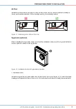
aV100 extract air system – Avio N 100
•
Installation and operating instructions
Requirements:
The masonry must be dry and in a load-bearing condition.
There must be no load-bearing elements at the location of the planned borehole/plaster or wall
slot.
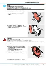
NOTE
Accumulation of condensation in the wall sleeve.
Damage to the exterior wall and masonry!
►
Create the wall opening with a slope of 1° to 2° to the exterior wall.
TIP
Ensure that you position the wall opening properly (see section 3.2).
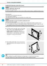
Standard model: create the wall opening with at least 250 mm distance from adjacent compo-
nents in order to install the inner cover and weather protection hood correctly.
Corner model: create the wall opening with at least 200 mm distance from bottom edge of the
reveal (lintel) and interior adjacent components in order to install the inner cover and the reveal
grille correctly. (Note the insulation thickness and possibly shutters)
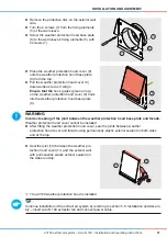
With both models, take care not to create the wall opening in the vicinity of radiators/heaters and
keep a minimum frontal clearance of 300 mm, otherwise maintenance work cannot be carried
out.
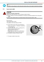
TIP
Ensure that the plaster/masonry slot is 45 ° above and to the right of the wall opening to ensure
correct installation of the power cable.
Ö
Ö
The wall opening for the wall sleeve and the plaster/masonry slot have been created.
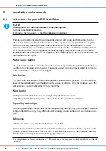
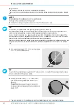
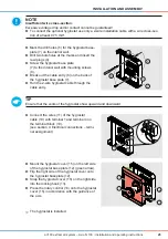
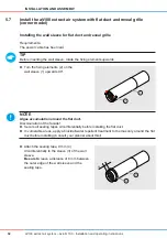
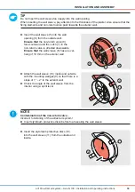
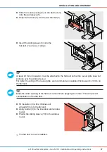
►
Drill a wall opening, Ø 115 mm (1) with a slope
of 1° – 2° to the exterior wall.
Ø
115
1
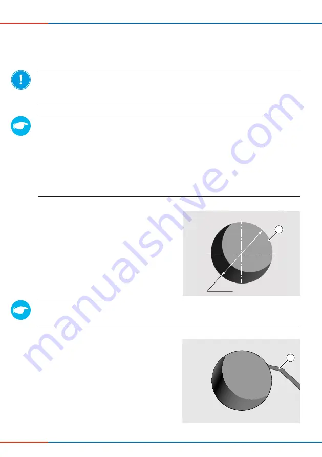
►
Mill the plaster/masonry slot (2).between the
light switch/switch/pushbutton and the wall
opening.
Ensure that
the plaster/masonry slot (2) for
the power cable is located at the top right at an
angle of 45°.
2


