


18
ELECTRICAL CONNECTIONS
aV100 extract air system – Avio N 100
•
Installation and operating instructions
4
Electrical connections
DANGER
Exposed electrical components.
Electric shock and injury due to live components (230V, 50Hz)!
►
Before working on electrical installations, disconnect all affected equipment from the power
supply.
DANGER
Ingress of water into aV100 extract air system or its components/power source.
Electric shock and overheating due to short circuit (230V, 50Hz)!
►
Install aV100 extract air system outside protection area 0.
►
Install the power source for the aV100 extract air system outside protection areas 0 to 2.
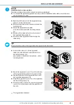
NOTE
Insufficient wire cross-section.
Excessive voltage drop and/or contact cannot be guaranteed!
►
For the power cable use a wire cross-section of 1.5 mm².
►
To connect the optional hygrostat use a 2-wire installation cable with a wire cross-section of
at least 0.75 mm².
TIP
The aV100 extract air system can be combined with a light switch (2-pole) or connected to a
standard switch/pushbutton. This is not supplied with the aV100 extract air system and must be
provided by the customer.
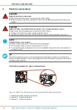
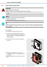
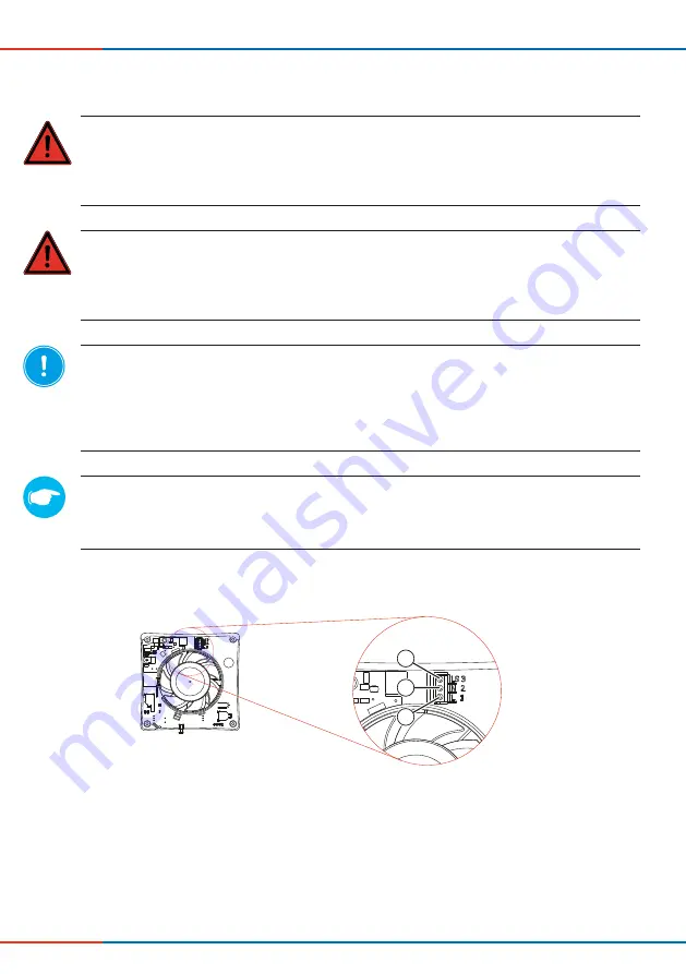
Terminal assignment for power cable terminal
Figure 19: PCB for Avio N 100 extractor fan: terminal assignment for power cable terminal
1
3
2
1 Terminal LS (phase conductor, switched)
2 Terminal N (neutral conductor)
3 Terminal L (phase conductor)


