


19
ELECTRICAL CONNECTIONS
aV100 extract air system – Avio N 100
•
Installation and operating instructions
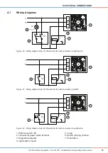
4.1
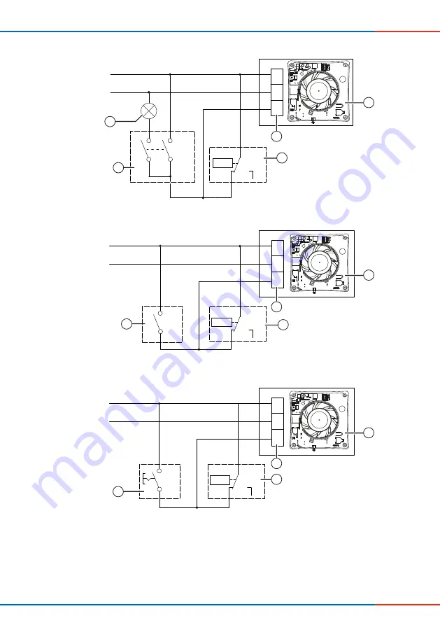
Wiring diagrams
Figure 20: Wiring diagram: Avio N 100 extractor fan with connection to light switch
Figure 21: Wiring diagram: Avio N 100 extractor fan with connection to switch
Figure 22: Wiring diagram: Avio N 100 extractor fan with connection to pushbutton
L
N
N
L
Ls
La
S1
% rF
1
4
2
1
2
4
5
3
L
N
N
L
Ls
S1
% rF
1
4
2
1
2
6
3
L
N
N
L
Ls
S1
% rF
1
4
2
1
2
7
3
1 PCB for Avio N 100
2 Terminal for power cable terminal
3 Hygrostat (optional)
4 Light switch, 2-pole
5 Lamp
6 Switch (closing contact)
7 Pushbutton


