


Board Level PWM and Fan Speed Control Requirements
R
Thermal/Mechanical Design Guide
87
Appendix E Board Level PWM and Fan
Speed Control
Requirements
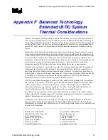
To use all of the features in the Intel reference heatsink design or the Boxed Intel Pentium 4
Processor in 775–land LGA package, system integrators should verify the following functionality
is present in the board design. Refer to the
Fan Specification for 4 wire PWM Controlled Fans
and Chapter 5 for complete details on the Intel enabled thermal solution.
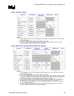
The basics of Fan Speed Control are discussed in Chapter 6; as a review, the FSC definitions are
listed in Table 7.
Table 7. FSC Definitions
Item Definition
T
DIODE
Temperature reported from the processor on-die thermal diode.
T
CONTROL
T
CONTROL
is the specification limit for use with the on-die thermal diode
T
LOW
The temperature above which the fan will begin to accelerate in response to the on-die
thermal diode temperature.
Hysteresis
The number of degrees below T-control the fans will remain on before slowing down.
T
HIGH
The temperature at which the fan is operating at full speed (100% PWM Duty Cycle). By
specification this is T
CONTROL
.
All Fans ON
The processor temperature at which all fans in the system are increased to 100% Duty
Cycle.
Min PWM
Minimum pulse width modulation (% duty cycle) that the fans will run at when T
DIODE
is less
than T
LOW
.
Spin-up
Amount of time fan is run at 100% duty cycle to overcome fan inertia.
PWM Freq
The operating frequency of the PWM signal.
T
AVERAGING
The time (in seconds) that elapses while the fan is gradually sped up in response to a
processor temperature spike.
Содержание 640 - Pentium 4 640 3.2GHz 800MHz 2MB Socket 775 CPU
Страница 14: ...Introduction R 14 Thermal Mechanical Design Guide ...
Страница 38: ...Thermal Management Logic and Thermal Monitor Feature R 38 Thermal Mechanical Design Guide ...
Страница 52: ...Intel Thermal Mechanical Reference Design Information R 52 Thermal Mechanical Design Guide ...
Страница 60: ...Acoustic Fan Speed Control R 60 Thermal Mechanical Design Guide ...
Страница 72: ...Heatsink Clip Load Metrology R 72 Thermal Mechanical Design Guide ...
Страница 97: ...Mechanical Drawings R Thermal Mechanical Design Guide 97 Figure 48 Reference Clip Drawings Sheet 1 ...
Страница 98: ...Mechanical Drawings R 98 Thermal Mechanical Design Guide Figure 49 Reference Clip Drawings Sheet 2 ...
Страница 99: ...Mechanical Drawings R Thermal Mechanical Design Guide 99 Figure 50 Reference Fastener Sheet 1 ...
Страница 100: ...Mechanical Drawings R 100 Thermal Mechanical Design Guide Figure 51 Reference Fastener Sheet 2 ...
Страница 101: ...Mechanical Drawings R Thermal Mechanical Design Guide 101 Figure 52 Reference Fastener Sheet 3 ...
Страница 102: ...Mechanical Drawings R 102 Thermal Mechanical Design Guide Figure 53 Reference Fastener Sheet 4 ...
Страница 103: ...Mechanical Drawings R Thermal Mechanical Design Guide 103 Figure 54 Clip Heatsink Assembly ...
Страница 104: ...Mechanical Drawings R 104 Thermal Mechanical Design Guide Figure 55 Intel R RCBFH 3 Reference Solution Assembly ...


