


Thermal Management Logic and Thermal Monitor Feature
R
Thermal/Mechanical Design Guide
37
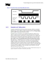
4.2.8 THERMTRIP#
Signal
In the event of a catastrophic cooling failure, the processor will automatically shut down when the
silicon temperature has reached its operating limit. At this point the system bus signal
THERMTRIP# goes active and power must be removed from the processor. THERMTRIP#
activation is independent of processor activity and does not generate any bus cycles. Refer to the
datasheet
for more information about THERMTRIP#.
The temperature where the THERMTRIP# signal goes active is individually calibrated during
manufacturing. The temperature where THERMTRIP# goes active is roughly parallel to the
thermal profile and greater than the PROCHOT# activation temperature. Once configured, the
temperature at which the THERMTRIP# signal is asserted is neither re-configurable nor
accessible to the system.
4.2.8.1
Cooling System Failure Warning
It may be useful to use the PROCHOT# signal as an indication of cooling system failure.
Messages could be sent to the system administrator to warn of the cooling failure, while the
thermal control circuit would allow the system to continue functioning or allow a normal system
shutdown. If no thermal management action is taken, the silicon temperature may exceed the
operating limits, causing THERMTRIP# to activate and shut down the processor. Regardless of
the system design requirements or thermal solution ability, the Thermal Monitor feature must still
be enabled to ensure proper processor operation.
§
Содержание 640 - Pentium 4 640 3.2GHz 800MHz 2MB Socket 775 CPU
Страница 14: ...Introduction R 14 Thermal Mechanical Design Guide ...
Страница 38: ...Thermal Management Logic and Thermal Monitor Feature R 38 Thermal Mechanical Design Guide ...
Страница 52: ...Intel Thermal Mechanical Reference Design Information R 52 Thermal Mechanical Design Guide ...
Страница 60: ...Acoustic Fan Speed Control R 60 Thermal Mechanical Design Guide ...
Страница 72: ...Heatsink Clip Load Metrology R 72 Thermal Mechanical Design Guide ...
Страница 97: ...Mechanical Drawings R Thermal Mechanical Design Guide 97 Figure 48 Reference Clip Drawings Sheet 1 ...
Страница 98: ...Mechanical Drawings R 98 Thermal Mechanical Design Guide Figure 49 Reference Clip Drawings Sheet 2 ...
Страница 99: ...Mechanical Drawings R Thermal Mechanical Design Guide 99 Figure 50 Reference Fastener Sheet 1 ...
Страница 100: ...Mechanical Drawings R 100 Thermal Mechanical Design Guide Figure 51 Reference Fastener Sheet 2 ...
Страница 101: ...Mechanical Drawings R Thermal Mechanical Design Guide 101 Figure 52 Reference Fastener Sheet 3 ...
Страница 102: ...Mechanical Drawings R 102 Thermal Mechanical Design Guide Figure 53 Reference Fastener Sheet 4 ...
Страница 103: ...Mechanical Drawings R Thermal Mechanical Design Guide 103 Figure 54 Clip Heatsink Assembly ...
Страница 104: ...Mechanical Drawings R 104 Thermal Mechanical Design Guide Figure 55 Intel R RCBFH 3 Reference Solution Assembly ...


