


Acoustic Fan Speed Control
R
56
Thermal/Mechanical Design Guide
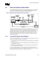
Figure 18. Fan Speed Control
Diode Temperature
(°C)
T
CONTROL
Min Speed
Fa
n S
peed
(RPM)
Full Speed
T
LOW
X %
Fa
n S
peed
(%
P
W
M D
u
ty
Cy
cle)
100 %
Diode Temperature
(°C)
T
CONTROL
Min Speed
Fa
n S
peed
(RPM)
Full Speed
T
LOW
X %
Fa
n S
peed
(%
P
W
M D
u
ty
Cy
cle)
100 %
6.3.1.1 Temperature
to
begin Fan Acceleration
The first item to consider is the value for T
LOW
. The FSC device needs a minimum temperature to
set as the threshold to begin increasing PWM duty cycle to the fan.
The system designer might initially consider a small temperature range
(T
CONTROL
– T
LOW
= T
RANGE
), such as 5 °C to accelerate the fan. That would delay the fan
accelerating for the longest period after an increase in T
DIODE
. There are a number of issues that
should be considered with this strategy:
•
There is little granularity in the fan speeds. For each 1 °C of increase in diode
temperature = 20% jump in PWM duty cycle %.
•
Fan speed oscillation as the thermal solution chases the diode temperature.
•
Having T
DIODE
overshoot T
CONTROL
and the thermal profile causing the Thermal Control
Circuit to activate to reduce the temperature.
The first two cases can create a poor acoustic response for the user. For the third case, the user
could notice a drop in performance as the thermal control circuit reduces the power. Figure 19 is
an example of this situation. The system begins at idle and a moderate workload is applied (less
than TDP).
Содержание 640 - Pentium 4 640 3.2GHz 800MHz 2MB Socket 775 CPU
Страница 14: ...Introduction R 14 Thermal Mechanical Design Guide ...
Страница 38: ...Thermal Management Logic and Thermal Monitor Feature R 38 Thermal Mechanical Design Guide ...
Страница 52: ...Intel Thermal Mechanical Reference Design Information R 52 Thermal Mechanical Design Guide ...
Страница 60: ...Acoustic Fan Speed Control R 60 Thermal Mechanical Design Guide ...
Страница 72: ...Heatsink Clip Load Metrology R 72 Thermal Mechanical Design Guide ...
Страница 97: ...Mechanical Drawings R Thermal Mechanical Design Guide 97 Figure 48 Reference Clip Drawings Sheet 1 ...
Страница 98: ...Mechanical Drawings R 98 Thermal Mechanical Design Guide Figure 49 Reference Clip Drawings Sheet 2 ...
Страница 99: ...Mechanical Drawings R Thermal Mechanical Design Guide 99 Figure 50 Reference Fastener Sheet 1 ...
Страница 100: ...Mechanical Drawings R 100 Thermal Mechanical Design Guide Figure 51 Reference Fastener Sheet 2 ...
Страница 101: ...Mechanical Drawings R Thermal Mechanical Design Guide 101 Figure 52 Reference Fastener Sheet 3 ...
Страница 102: ...Mechanical Drawings R 102 Thermal Mechanical Design Guide Figure 53 Reference Fastener Sheet 4 ...
Страница 103: ...Mechanical Drawings R Thermal Mechanical Design Guide 103 Figure 54 Clip Heatsink Assembly ...
Страница 104: ...Mechanical Drawings R 104 Thermal Mechanical Design Guide Figure 55 Intel R RCBFH 3 Reference Solution Assembly ...


