


Case Temperature Reference Metrology
R
84
Thermal/Mechanical Design Guide
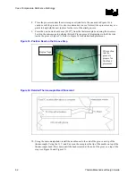
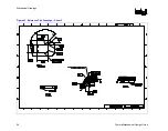
Figure 37. Applying the Adhesive on the Thermocouple Bead
13.
Measure the resistance from the thermocouple end wires again using the DMM (refer to
Section D.6.1, step 2) and to ensure the bead is still properly contacting the IHS.
D.6.3 Curing
Process
14.
Let the thermocouple attach set in the open-air for at least 1/2 Hr. It is not recommended to
use any curing accelerator like Loctite Accelerator 7452 for this step, as rapid contraction of
the adhesive during curing may weaken bead attach on the IHS.
15.
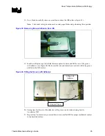
Reconfirm electrical connectivity with DMM before removing the micromanipulator
(Figure 36) ( see Section D.6.1, step 2 and above).
16.
Remove the 3D Arm needle by holding down the processor unit and lifting the arm.
17.
Remove the Kapton tape, straighten the wire in the groove so it lays flat all the way to the
end of the groove Figure 38.
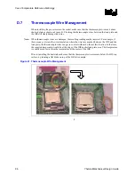
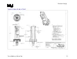
Figure 38. Thermocouple Wire Management in the Groove
Содержание 640 - Pentium 4 640 3.2GHz 800MHz 2MB Socket 775 CPU
Страница 14: ...Introduction R 14 Thermal Mechanical Design Guide ...
Страница 38: ...Thermal Management Logic and Thermal Monitor Feature R 38 Thermal Mechanical Design Guide ...
Страница 52: ...Intel Thermal Mechanical Reference Design Information R 52 Thermal Mechanical Design Guide ...
Страница 60: ...Acoustic Fan Speed Control R 60 Thermal Mechanical Design Guide ...
Страница 72: ...Heatsink Clip Load Metrology R 72 Thermal Mechanical Design Guide ...
Страница 97: ...Mechanical Drawings R Thermal Mechanical Design Guide 97 Figure 48 Reference Clip Drawings Sheet 1 ...
Страница 98: ...Mechanical Drawings R 98 Thermal Mechanical Design Guide Figure 49 Reference Clip Drawings Sheet 2 ...
Страница 99: ...Mechanical Drawings R Thermal Mechanical Design Guide 99 Figure 50 Reference Fastener Sheet 1 ...
Страница 100: ...Mechanical Drawings R 100 Thermal Mechanical Design Guide Figure 51 Reference Fastener Sheet 2 ...
Страница 101: ...Mechanical Drawings R Thermal Mechanical Design Guide 101 Figure 52 Reference Fastener Sheet 3 ...
Страница 102: ...Mechanical Drawings R 102 Thermal Mechanical Design Guide Figure 53 Reference Fastener Sheet 4 ...
Страница 103: ...Mechanical Drawings R Thermal Mechanical Design Guide 103 Figure 54 Clip Heatsink Assembly ...
Страница 104: ...Mechanical Drawings R 104 Thermal Mechanical Design Guide Figure 55 Intel R RCBFH 3 Reference Solution Assembly ...


