


Acoustic Fan Speed Control
R
58
Thermal/Mechanical Design Guide
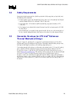
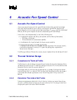
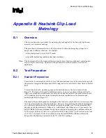
Figure 20. Temperature Range = 10 °C
0
500
1000
1500
2000
2500
3000
3500
Time (s)
RP
M
40
45
50
55
60
65
70
75
80
T
d
io
d
e
(
C
)
Fan RPM
Tdiode
Tcontrol
Tlow
It should be noted that having T
DIODE
above T
CONTROL
is expected for near TDP power levels and
high system ambient. See Section 6.5 for additional discussion on T
CONTROL
versus Thermal
Profile.
For use with the Intel
®
Boxed Pentium 4 Processor in 775–Land LGA Package on the enabled
reference solution, a T
RANGE
value of 10 °C is recommended for ATX chassis.
6.3.1.2
Minimum PWM Duty Cycle
The final step in determining the FSC setting is to determine the minimum PWM Duty cycle. This
is the fan speed for any T
DIODE
< T
LOW
. The selection of this value is dependent on:
•
Acoustic target at system idle
•
Voltage regulator cooling
For a motherboard design intending to use the Intel Boxed Pentium 4 Processor in 775–land LGA
Package or the enabled reference thermal solution the recommended minimum PWM duty cycle
is 30%.
Содержание 640 - Pentium 4 640 3.2GHz 800MHz 2MB Socket 775 CPU
Страница 14: ...Introduction R 14 Thermal Mechanical Design Guide ...
Страница 38: ...Thermal Management Logic and Thermal Monitor Feature R 38 Thermal Mechanical Design Guide ...
Страница 52: ...Intel Thermal Mechanical Reference Design Information R 52 Thermal Mechanical Design Guide ...
Страница 60: ...Acoustic Fan Speed Control R 60 Thermal Mechanical Design Guide ...
Страница 72: ...Heatsink Clip Load Metrology R 72 Thermal Mechanical Design Guide ...
Страница 97: ...Mechanical Drawings R Thermal Mechanical Design Guide 97 Figure 48 Reference Clip Drawings Sheet 1 ...
Страница 98: ...Mechanical Drawings R 98 Thermal Mechanical Design Guide Figure 49 Reference Clip Drawings Sheet 2 ...
Страница 99: ...Mechanical Drawings R Thermal Mechanical Design Guide 99 Figure 50 Reference Fastener Sheet 1 ...
Страница 100: ...Mechanical Drawings R 100 Thermal Mechanical Design Guide Figure 51 Reference Fastener Sheet 2 ...
Страница 101: ...Mechanical Drawings R Thermal Mechanical Design Guide 101 Figure 52 Reference Fastener Sheet 3 ...
Страница 102: ...Mechanical Drawings R 102 Thermal Mechanical Design Guide Figure 53 Reference Fastener Sheet 4 ...
Страница 103: ...Mechanical Drawings R Thermal Mechanical Design Guide 103 Figure 54 Clip Heatsink Assembly ...
Страница 104: ...Mechanical Drawings R 104 Thermal Mechanical Design Guide Figure 55 Intel R RCBFH 3 Reference Solution Assembly ...


