


Board Level PWM and Fan Speed Control Requirements
R
88
Thermal/Mechanical Design Guide
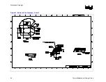
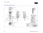
Figure 42. FSC Definitions Example
Requirements Classification
•
Required – an essential part of the design necessary to meet specifications. Should be
considered a pass or fail criterion in selection of a board.
•
Suggested – highly desired for consistency among designs. May be specified or expanded by
the system integrator.
The motherboard needs to have a fan speed control component that has the following
characteristics:
•
PWM output programmable to 21–28 kHz (required). PWM output set to 25 kHz (Suggested)
as this value is the design target for the reference and for the Boxed Pentium 4 Processor.
•
External/remote thermal diode measurement capability (required).
•
External/remote thermal diode sampling rate
≥
4 times per second (required).
•
External/remote diode measurement is calibrated by the component vendor to account for the
diode ideality and package series resistance as listed in the appropriate datasheet.
(Suggested).
Note:
If the fan speed controller is not calibrated with the diode ideality and package series resistance,
verify the board manufacturer has made provisions within the BIOS setup or other utility to input
the corrections factors.
Note:
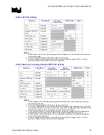
The BIOS, at a minimum, must program the settings in Table 8 or Table 9 into the fan speed
controller. The values are the minimum required to establish a fan speed control algorithm
consistent with this document, the reference thermal solution and Boxed Processor thermal
solution.
Содержание 640 - Pentium 4 640 3.2GHz 800MHz 2MB Socket 775 CPU
Страница 14: ...Introduction R 14 Thermal Mechanical Design Guide ...
Страница 38: ...Thermal Management Logic and Thermal Monitor Feature R 38 Thermal Mechanical Design Guide ...
Страница 52: ...Intel Thermal Mechanical Reference Design Information R 52 Thermal Mechanical Design Guide ...
Страница 60: ...Acoustic Fan Speed Control R 60 Thermal Mechanical Design Guide ...
Страница 72: ...Heatsink Clip Load Metrology R 72 Thermal Mechanical Design Guide ...
Страница 97: ...Mechanical Drawings R Thermal Mechanical Design Guide 97 Figure 48 Reference Clip Drawings Sheet 1 ...
Страница 98: ...Mechanical Drawings R 98 Thermal Mechanical Design Guide Figure 49 Reference Clip Drawings Sheet 2 ...
Страница 99: ...Mechanical Drawings R Thermal Mechanical Design Guide 99 Figure 50 Reference Fastener Sheet 1 ...
Страница 100: ...Mechanical Drawings R 100 Thermal Mechanical Design Guide Figure 51 Reference Fastener Sheet 2 ...
Страница 101: ...Mechanical Drawings R Thermal Mechanical Design Guide 101 Figure 52 Reference Fastener Sheet 3 ...
Страница 102: ...Mechanical Drawings R 102 Thermal Mechanical Design Guide Figure 53 Reference Fastener Sheet 4 ...
Страница 103: ...Mechanical Drawings R Thermal Mechanical Design Guide 103 Figure 54 Clip Heatsink Assembly ...
Страница 104: ...Mechanical Drawings R 104 Thermal Mechanical Design Guide Figure 55 Intel R RCBFH 3 Reference Solution Assembly ...


