


Processor Thermal/Mechanical Information
R
Thermal/Mechanical Design Guide
19
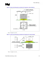
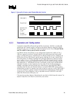
Figure 2. Processor Case Temperature Measurement Location
37.5 mm
Measure T
C
at this point
(geometric center of the package)
3
7
.5
m
m
37.5 mm
Measure T
C
at this point
(geometric center of the package)
3
7
.5
m
m
2.2.2 Thermal
Profile
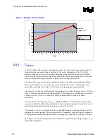
The Thermal Profile defines the maximum case temperature as a function of processor power
dissipation. The TDP and Maximum Case Temperature are defined as the maximum values of the
thermal profile. By design the thermal solutions must meet the thermal profile for all system
operating conditions and processor power levels.
The slope of the thermal profile was established assuming a generational improvement in thermal
solution performance of about 10% based on previous Intel reference designs. This performance
is expressed as the slope on the thermal profile and can be thought of as the thermal resistance of
the heatsink attached to the processor,
Ψ
CA
(Refer to Section 3.1). The intercept on the thermal
profile assumes a maximum ambient operating condition that is consistent with the available
chassis solutions.
To determine compliance to the thermal profile, a measurement of the actual processor power
dissipation is required. Contact your Intel sales representative for assistance in processor power
measurement. The measured power is plotted on the Thermal Profile to determine the maximum
case temperature. Using the example in Figure 3 for a processor dissipating 70 W the maximum
case temperature is 61 °C.
For the Pentium 4 processor in the 775–land LGA package, there are two thermal profiles to
consider. The Platform Requirement Bit (PRB) indicates which thermal profile is appropriate for
a specific processor. This document will focus on the development of thermal solutions to meet
the thermal profile for PRB=1. See the processor datasheet for the thermal profile and additional
discussion on the PRB.
Содержание 640 - Pentium 4 640 3.2GHz 800MHz 2MB Socket 775 CPU
Страница 14: ...Introduction R 14 Thermal Mechanical Design Guide ...
Страница 38: ...Thermal Management Logic and Thermal Monitor Feature R 38 Thermal Mechanical Design Guide ...
Страница 52: ...Intel Thermal Mechanical Reference Design Information R 52 Thermal Mechanical Design Guide ...
Страница 60: ...Acoustic Fan Speed Control R 60 Thermal Mechanical Design Guide ...
Страница 72: ...Heatsink Clip Load Metrology R 72 Thermal Mechanical Design Guide ...
Страница 97: ...Mechanical Drawings R Thermal Mechanical Design Guide 97 Figure 48 Reference Clip Drawings Sheet 1 ...
Страница 98: ...Mechanical Drawings R 98 Thermal Mechanical Design Guide Figure 49 Reference Clip Drawings Sheet 2 ...
Страница 99: ...Mechanical Drawings R Thermal Mechanical Design Guide 99 Figure 50 Reference Fastener Sheet 1 ...
Страница 100: ...Mechanical Drawings R 100 Thermal Mechanical Design Guide Figure 51 Reference Fastener Sheet 2 ...
Страница 101: ...Mechanical Drawings R Thermal Mechanical Design Guide 101 Figure 52 Reference Fastener Sheet 3 ...
Страница 102: ...Mechanical Drawings R 102 Thermal Mechanical Design Guide Figure 53 Reference Fastener Sheet 4 ...
Страница 103: ...Mechanical Drawings R Thermal Mechanical Design Guide 103 Figure 54 Clip Heatsink Assembly ...
Страница 104: ...Mechanical Drawings R 104 Thermal Mechanical Design Guide Figure 55 Intel R RCBFH 3 Reference Solution Assembly ...


