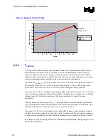


Thermal
Metrology
R
Thermal/Mechanical Design Guide
25
3 Thermal
Metrology
This chapter discusses guidelines for testing thermal solutions, including measuring processor
temperatures. In all cases, the thermal engineer must measure power dissipation and temperature
to validate a thermal solution. To define the performance of a thermal solution the “thermal
characterization parameter”,
Ψ
(“psi”) will be used.
3.1
Characterizing Cooling Performance Requirements
The idea of a “thermal characterization parameter”,
Ψ
(“psi”), is a convenient way to characterize
the performance needed for the thermal solution and to compare thermal solutions in identical
situations (same heat source and local ambient conditions). The thermal characterization
parameter is calculated using total package power.
Note:
Heat transfer is a three-dimensional phenomenon that can rarely be accurately and easily modeled
by a single resistance parameter like
Ψ
.
The case-to-local ambient thermal characterization parameter value (
Ψ
CA
) is used as a measure of
the thermal performance of the overall thermal solution that is attached to the processor package.
It is defined by the following equation, and measured in units of °C/W:
Ψ
CA
= (T
C
- T
A
) / P
D
(Equation 1)
Where:
Ψ
CA
= Case-to-local ambient thermal characterization parameter (°C/W)
T
C
= Processor case temperature (°C)
T
A
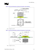
= Local ambient temperature in chassis at processor (°C)
P
D
= Processor total power dissipation (W) (assumes all power dissipates through the
IHS)
The case-to-local ambient thermal characterization parameter of the processor,
Ψ
CA
, is comprised
of
Ψ
CS
, the thermal interface material thermal characterization parameter, and of
Ψ
SA
, the sink-to-
local ambient thermal characterization parameter:
Ψ
CA
=
Ψ
CS
+
Ψ
SA
(Equation 2)
Where:
Ψ
CS
= Thermal characterization parameter of the thermal interface material (°C/W)
Ψ
SA
= Thermal characterization parameter from heatsink-to-local ambient (°C/W)
Содержание 640 - Pentium 4 640 3.2GHz 800MHz 2MB Socket 775 CPU
Страница 14: ...Introduction R 14 Thermal Mechanical Design Guide ...
Страница 38: ...Thermal Management Logic and Thermal Monitor Feature R 38 Thermal Mechanical Design Guide ...
Страница 52: ...Intel Thermal Mechanical Reference Design Information R 52 Thermal Mechanical Design Guide ...
Страница 60: ...Acoustic Fan Speed Control R 60 Thermal Mechanical Design Guide ...
Страница 72: ...Heatsink Clip Load Metrology R 72 Thermal Mechanical Design Guide ...
Страница 97: ...Mechanical Drawings R Thermal Mechanical Design Guide 97 Figure 48 Reference Clip Drawings Sheet 1 ...
Страница 98: ...Mechanical Drawings R 98 Thermal Mechanical Design Guide Figure 49 Reference Clip Drawings Sheet 2 ...
Страница 99: ...Mechanical Drawings R Thermal Mechanical Design Guide 99 Figure 50 Reference Fastener Sheet 1 ...
Страница 100: ...Mechanical Drawings R 100 Thermal Mechanical Design Guide Figure 51 Reference Fastener Sheet 2 ...
Страница 101: ...Mechanical Drawings R Thermal Mechanical Design Guide 101 Figure 52 Reference Fastener Sheet 3 ...
Страница 102: ...Mechanical Drawings R 102 Thermal Mechanical Design Guide Figure 53 Reference Fastener Sheet 4 ...
Страница 103: ...Mechanical Drawings R Thermal Mechanical Design Guide 103 Figure 54 Clip Heatsink Assembly ...
Страница 104: ...Mechanical Drawings R 104 Thermal Mechanical Design Guide Figure 55 Intel R RCBFH 3 Reference Solution Assembly ...