3. Electrical Installation
- 64 -
3
Ƶ
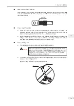
Braking Resistor
CAUTION
Ɣ
Fire risk! Fit overtemperature sensors or thermal overload relay to
the braking resistor, and use double insulated cables for the dynamic
brake circuit to the brake resistors.
Ɣ
Braking resistor terminals (+) and PB are only for the drive units up to
N:WKDWDUH¿WWHGZLWKDQLQWHUQDOEUDNLQJXQLW
Ɣ
To avoid risk of equipment damage, use a cable not exceeding 5 m to
connect an external braking resistor.
Ɣ
To avoid risk of ignition due to overheating of the braking resistor, do
not place anything combustible around the braking resistor.
Ɣ
Set F6-15 (Braking use ratio) and F9-08 (Braking unit action initial
voltage) correctly according to load after connecting braking resistor to
WKHGULYHRIXSWRN:WKDWLV¿WWHGZLWKDQLQWHUQDOEUDNLQJXQLW
Ƶ
AC Drive Outputs U, V, W to Motor
Grounding clamp
for screen/shield
Main circuit cables
Cable support
bracket (option)
Use heatshrink tube or
insulation tape to terminate
the screen/shield.
Screen/shield
Содержание MD290 Series
Страница 1: ......
Страница 79: ...3 Electrical Installation 78 3 ...
Страница 80: ...4 Operating Panel Keypad Display 4 1 Introduction 80 4 2 Inbuilt LED Operating Panel 80 ...
Страница 92: ...5 Quick Setup 5 1 Get Familiar With Operating Panel 92 5 2 Setup Flowchart 93 ...
Страница 227: ...7 Interfaces and Communication 226 7 ...
Страница 285: ...10 Troubleshooting 284 11 ...
Страница 349: ......
Страница 350: ......


