

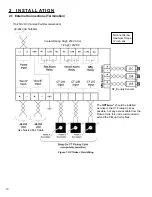


8
DC Input Channels
Two discrete voltage signals, 48-250 VDC. The “Aux A”
input is used to initiate the trip time log, the mechanism
time log, the arc duration time log, and the cumulative
I
2
T or I T duty log. The “Aux B” input is used to stop the
mechanism time log.
A continuous interrogation process detects Aux input logic
failure when both inputs are asserted or de-asserted at
the same time for longer than 3 seconds. This conflicting
input would indicate a serious problem with the circuit, DC
power has been lost, a wire is broken, etc. This condition
causes an “A-B Logic” alarm.
EVENT TRIGGERING
•
TRIP TIME
(opening time log) – (Available in
INPUT MODEs 2 & 4 only.) The start is triggered by
a positive assertion (rising edge) to the Aux A input.
The stop is triggered by the de-assertion (falling
edge) of the Aux A input, with the actual buffer stop
time adjusted by the software setting
A INPUT
DELAY
, which accounts for the time difference
between the Aux A de-assertion and the actual
parting of the main contacts.
•
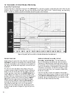
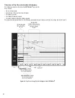
ARC TIME
(arc duration log) – maximum duration
is 10 cycles per trip operation; the start time is
indexed by an assertion of the Aux A input, with the
actual buffer start time adjusted by the software
setting
A INPUT DELAY
, which accounts for
the time difference between the Aux A assertion
and the actual parting of the main contacts. A
proprietary algorithm that detects the end of arc
current in all three phases triggers the stop. See
Figure 6.
•
CLEARING TIME
(interrupting time log) –
(Available in INPUT MODEs 2 & 4 only.) The start
is triggered by the assertion (rising edge) of the Aux
A input. A proprietary algorithm that detects the end
of arc current in all three phases triggers the stop.
•
TRAVEL TIME
(mechanism time log) – (Available
in INPUT MODEs 1 & 4 only.) maximum duration is
10 cycles per trip operation; the start is triggered by
a change in state of the Aux A input. An assertion to
the Aux B input triggers the stop.
•
CLOSING TIME
(mechanism time log) – (Available
in INPUT MODE 1 only.) maximum duration is 10
cycles per trip operation; the start is triggered by
an assertion to the Aux B input. An assertion to the
Aux A input triggers the stop.
•
MAIN CONTACT ARCING DUTY LIFE
(phase
segregated I
2
T or I T per trip operation and phase
cumulative
I
2
T or I T data log); A mathematically
calculated value representative of the destructive
arc energy.
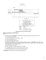
FIELD OUTPUTS
Visual Display
On-board LEDs will illuminate and latch when reaching an
alarm setpoint or detecting a failure mode. These may be
reset by software command.
The circuit breaker OPEN / CLOSED status is also
shown by green and red LEDs on the
OPTI
mizer
2
. This
OPEN / CLOSED status indicator should only be used as a
secondary indication and to verify correct programming of
A INPUT POLARITY
and
B INPUT POLARITY
assertion
states.
An LED bar graph alternates every 10 seconds between
indicating the remaining contact life and the SF
6
gas level.
In both cases, the condition of the worst phase is displayed.
When more than one LED is lit, the contact life is being
displayed. When a single LED is lit, the SF
6
level is being
displayed.
The scale is -50% to +100% for contact life. The scale for SF
6
gas level is based upon the programmed SF
6
Fill (density
or pressure), the Low Gas Warning Limit and the low Gas
Alarm Limit.
When displaying remaining contact life, the green zone is
scaled from 100% remaining life to the Warning Limit. The
yellow zone is scaled from the Warning Limit to the Danger
Limit (0% life). The red zone is scaled from the Danger Limit
to 50% below the Limit.
When displaying SF
6
gas level, the green zone is scaled from
the Fill (density or pressure) value to the Low Gas Warning
Limit. The yellow zone is scaled from the Low Gas Warning
Limit to the Low Gas Alarm Limit. The red zone is scaled from
the Low Gas Alarm Limit to zero (pressure or density).
When the display is in the green zone, the LED(s) will be
lit continuously. When the display is in the yellow zone, the
LED(s) will flash slowly to indicate an approaching alarm
condition. When the display is in the red zone, the LED(s) will
flash rapidly to indicate an alarm condition exists. A slowly
flashing green heartbeat LED indicates that the
OPTI
mizer²
system is functioning normally.
Relay Contacts
Two Form C relays and one Form A relay are provided
for alarms. The dry contacts are rated for 3A at 250 VAC
or 1 / 2A at 125VDC. These contacts are not intended
for breaking DC inductive loads. (For Alarm / relay
assignments, see Figure 8):
• The “RED” relay asserts when a Restrike or excess arc
duration is detected, or when the Contact Life Danger
limit is reached.
• The “YELLOW” relay asserts when a failed CT pickup
coil is detected, the Contact Life Warning limit is
reached, the Operations Count limit is reached, the
open or close mechanism time limit is reached, the Trip
Time limit is reached, the Clearing Time limit is reached,
the No Operations time limit is reached, or an A-B Logic
Alarm condition occurs.
• The SF
6
relay asserts when a Low Gas Alarm limit or
Trend Alarm limit is reached or if there is a malfunction
of the SF
6
sensor.


