


41
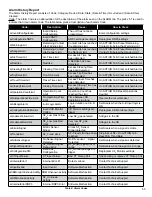
Input Mode
Entering the Input Mode, in combination with the A Input
Polarity and B Input Polarity, allows The
OPTI
mizer
2
to
monitor the
circuit breaker control circuit’s logic states
in the closed and open positions. The Input Mode also
governs whether or not Trip Time, Clearing Time, Travel
Time and Closing Time are measured.
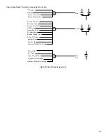
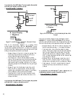
If the B Input is not wired, Input Modes 2 or 3 must be
used, depending upon the wiring of the A Input. Mode 3 is
used when the A Input signal is a continuous source, as
shown in Figures 12, 13 and 15. Mode 2 is used when the
A Input signal is a momentary (pulse) source, as shown in
Figure 14.
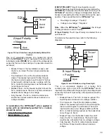
If the A Input is wired as shown in Figures 12, 13 or 15,
then Input Modes 1 or 3 must be used, depending upon
the wiring of the B Input: Mode 1 is used when the B Input
is wired. Mode 3 is used when the B Input is not wired.
If the A Input is wired across the trip coil, as shown
in Figure 14, then Input Modes 2 or 4 must be used,
depending upon the wiring of the B Input: Mode 2 is used
when the B Input is not wired. Mode 4 is used when the B
Input is wired.
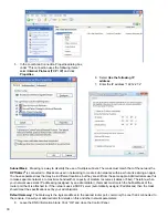
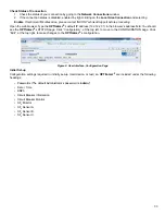
To set the Input Mode, select the CONFIGURATION tab
and click “EDIT”:
The Input Mode is selected from a pull-down list.
Mode 1 = Continuous A Signal with Continuous B
Signal
Mode 2 = Momentary A Signal, No B Signal
Mode 3 = Continuous A Signal, No B Signal
Mode 4 = Momentary A Signal with Continuous B
Signal
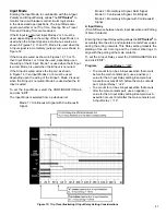
A Input Delay
(Time Difference between Aux A Input Assertion and Parting
of Main Contacts)
Entering the A Input Delay setting allows the
OPTI
mizer
2
to
accurately time the arcs, and calculate Contact Wear values
during the arcing intervals. This Delay setting impacts the
starting of the arc time log and the Contact Wear logs to
align with the parting of the main contacts.
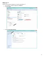
To set the A Input Delay, select the CONFIGURATION tab
and click “EDIT”:
Program:
A Input Delay = “-19”
• To account for an Aux A input assertion that occurs
before the main contacts part, use a positive (+)
value for the A Input Delay setting. Example: Aux
A assertion occurs 24 mS before the main contacts
part, A Input Delay = “+24”
• To account for an Aux A input assertion that occurs
after the main contacts part, use a negative (-)
value for the A Input Delay setting. Example: Aux A
assertion occurs 19 mS after the main contacts part,
A Input Delay = “-19”
Figure 19: Trip Trace illustrating A Input Delay Setting Considerations


