


20
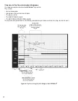
TRAVEL TIME (Mechanism Time Log) (Input Modes 1 & 4 only)
When INPUT MODE 1 or 4 is selected, the OPTImizer
²
will record mechanism TRAVEL TIME. The mechanism time log
consists of a timer. The timer starts from an assertion (or de-assertion in Mode 4) of the “Aux A” input, and stops with an
assertion to the “Aux B” input. The assertion levels are defined in software (
A INPUT POLARITY & B INPUT POLARITY
),
and are application-dependent.
It is possible to start the mechanism trip transit time log from one of two instances, either the trip initiate signal, or the
opening of the 52 / a contact.
Note:
The “Aux A” input is the common start for both the mechanism time log and the arc time log functions
.
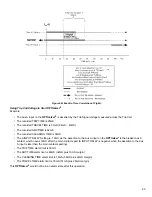
ARC TIME (Arc Time Log)
The individual, phase-segregated Arc Time logs employ a timer, starting with the main breaker contacts parting and
ending with the cessation of current in each phase.
Starting of the Arc Time Log
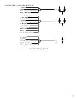
The arc time log is indexed to start with an assertion (or de-assertion in Modes 2 & 4) of the “Aux A” input. The assertion
level is defined in software (
A INPUT POLARITY
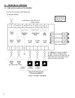
), and is application dependent. The actual starting of the log is
dependent on a setting used to adjust the time interval difference between the “Aux A” assertion and the actual parting of
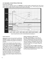
the mains. This adjustment time is referred to as
A INPUT DELAY
in Figure 6.
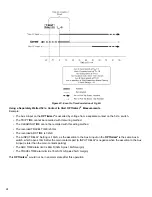
The A INPUT DELAY value may be either positive or negative, depending on if the “Aux A” assertion is later or earlier than
the mains parting:
• The adjustment time (A INPUT DELAY) is positive (+), if the mains part later than the “Aux A” assertion
• The adjustment time (A INPUT DELAY) is negative (-), if the mains part earlier than the “Aux A” assertion
Note
:
The “Aux A” input is the common start for both the mechanism time log and the arc time log functions.
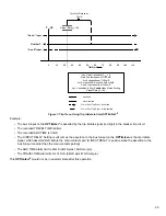
Stopping of the Arc Time Log
The arc time logs stop with the cessation of current in each phase. The cessation of current is determined by a proprietary
software algorithm which does waveform analysis in addition to checking for CT Secondary current falling below 7% of the
Pickup Coil full scale current rating for more than 8 consecutive samples (1 / 4 cycle).
Note
:
In instances where the CT Secondary phase currents are less than 7% of Pickup Coil full-scale current rating and
the breaker trips, an ARC TIME of 000 mS will be recorded.


