


38
OPTImizer
2
Aux A
Input
+
R
T/2
T/1
52/a
TC
Closed Open
A Input Polarity
= Positive
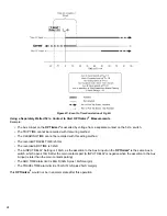
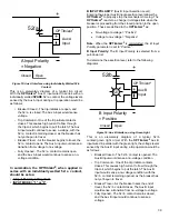
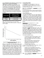
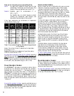
Figure 13: Aux A Interface, using 52 / a Contact in Trip Circuit
This is an elementary diagram of a typical trip circuit. The
elements T / 1 and T / 2 are trip-initiating contacts. These
could be from protective relays, manual trip switches,
SCADA contacts, etc. With the
OPTI
mizer
2
Aux A input
wired in parallel with the 52 / a contact in the trip circuit,
the voltage levels sensed by the Aux A input during a trip
operation would be as follows:
• Breaker Closed - The 52 / a contact is closed. The
Aux A input would sense a no-voltage condition, as
the voltage to the input is shunted.
• Trip Command - One of the trip initiate contacts
closes. This causes high current to flow through the
trip coil, which begins to pull the latch. The Aux A
input would sense a no-voltage condition, with the
52 / a contact remaining closed, as the breaker has
not yet begun to travel.
• Breaker Travel - As the breaker begins to travel, the
52 / a contact opens. The Aux A input would sense a
transition from no-voltage to voltage.
• Fully Opened - The 52 / a contact remains open, and
the Aux A input would continue to sense a voltage.
In summation, the OPTI
mizer
2
, when applied in parallel
with the 52 / a Contact in the trip circuit, should be set
as:
• A Input Polarity = “Positive”
• INPUT MODE = “1” or “3”.
OPTImizer
2
Aux A
Input
+
R
T/2
T/1
52/a
TC
Closed
Open
Trip
A Input Polarity
= Positive
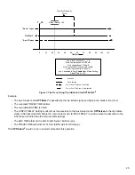
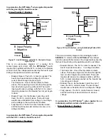
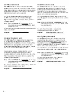
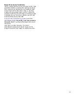
Figure 14: Aux A Interface, using Trip Coil Excitation Voltage
This is an elementary diagram of a typical trip circuit. The
elements T / 1 and T / 2 are trip-initiating contacts. These
could be from protective relays, manual trip switches,
SCADA contacts, etc. With the
OPTI
mizer
2
Aux A input
wired in parallel with the Trip Coil in the trip circuit, the
voltage levels sensed by the Aux A input during a trip
operation would be as follows:
• Breaker Closed - The 52 / a contact is closed. The
Aux A input would sense a low-voltage condition, as
the voltage dropped across the Trip Coil is minimal.
• Trip Command - One of the trip initiate contacts
closes. This causes high current to flow through the
trip coil, which begins to pull the latch. The Aux A
input would sense a high-voltage condition, with the
52 / a contact remaining closed, as the breaker has
not yet begun to travel.
• Breaker Travel - As the breaker begins to travel, the
52 / a contact opens. The Aux A input would sense a
transition from high-voltage to no-voltage.
• Fully Opened - The 52 / a contact remains open, and
the Aux A input would continue to sense no voltage.
In summation, the OPTI
mizer
2
, when applied in parallel
with the Trip Coil in the trip circuit, should be set as:
• A Input Polarity = “Positive”
• INPUT MODE = “2” or “4”.


