Idex HALE SmartCAFS Скачать руководство пользователя страница 109

Page 

109

 of 

116


©HALE PRODUCTS, INC. Our policy is one of continuous development. We therefore 

reserve the right to amend specifications without notice or obligation. 
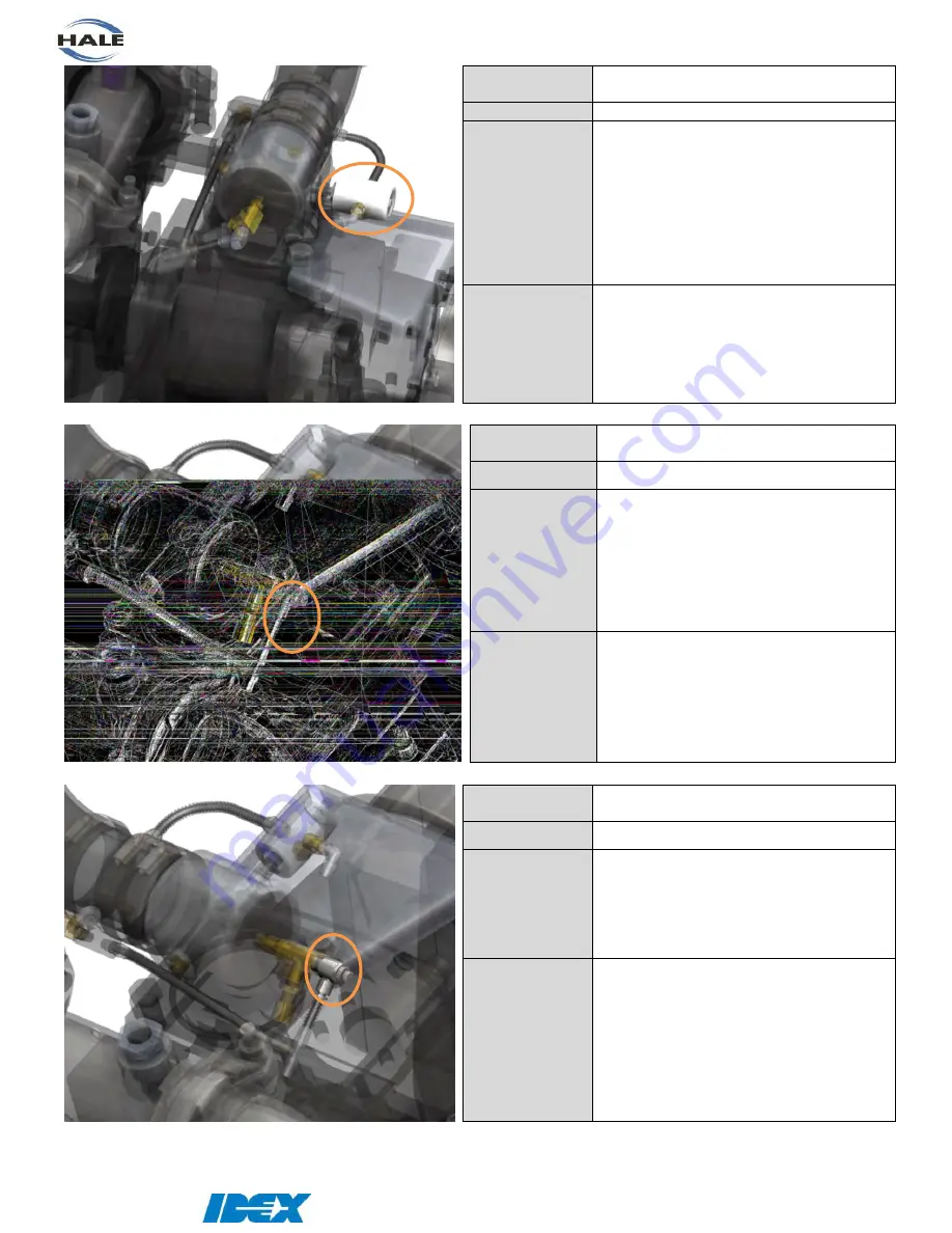
 

PART 

NUMBER 

038-1560-00-0 

DESCRIPTION 

Blow Down Valve 

OPERATION 

Releases built up pressure in air system.  

Air  pressure  is  supplied  from  the  oil 

separator and the air intake.  If they don’t 

match  the  valve  opens  connection  from 

the oil separator to atmosphere  

POSSIBLE 

FAULT 

  Air leaks 

o

  Valve is bad 

o

  Fittings are loose 


PART 

NUMBER 

038-00071-001 

DESCRIPTION 

Air Relief Valve 

OPERATION 

This  valve  relieves  pressure  from  the 

control side of the air intake valve.   Any 

pressure above the required pressure to 

close the air intake valve will be released.  

This improves the tracking speed for the 

pressure  match,  especially  when 

reducing water pressure. 

POSSIBLE 

FAULT 

  Pressure isn’t matching 

o

  Relief pressure is set too low.  

Tighten to increase relief 

pressure. 

  Air leaks 

o

  O-ring/Seal is bad 


PART 

NUMBER 

70141 

DESCRIPTION 

Air Intake Control Needle Valve 

OPERATION 

This  valve  controls  the  amount  of  air 

pressure limiting the air intake.  The larger 

the air pressure the lower the air flow into 

the  compressor.    It  also  dampens  the 

response of the air intake plunger. 

POSSIBLE 

FAULT 

  Air/Water tracking is not steady 

o

  Needle valve is open too far. 

  Air/Water tracking is too slow when 

changing water pressure 

o

  Needle valve is closed too far. 


See instructions on page 

89

. 


Содержание HALE SmartCAFS

Страница 1: ...ion and Operation Manual HALE PRODUCTS INC A Unit of IDEX Corporation 607 NW 27th Ave Ocala FL 34475 United States 800 533 3569 800 520 3473 www haleproducts com Halecustomerservice idexcorp com FSG MNL 00157 REV D July 2020 ...

Страница 2: ...UG2018 RAA 21 22 86 Add pictures of gear pump w new motor driver Changed separator element replacement kit QTY from 1 to 2 D 13JUL2020 JS2 10 16 22 40 44 49 60 95 105 108 111 Added Dual Foam data Updated manifolds Updated dimensional diagrams Updated FSG PL 01308 and FSG PL 01422 Added multi display setup operation instructions Added Auto Fill info layout and components Updated wiring diagram PL72...

Страница 3: ...LE 10 FOAM PROPORTIONING SYSTEM 6 5 CLASS A AND B FOAM COMPATIBLE 10 FOAM PROPORTIONING SYSTEM DUAL 6 5 CLASS A AND B FOAM COMPATIBLE 10 LUBRICANTS 11 COMPRESSOR SYSTEM 11 PUMP GEARBOX 11 CLUTCH HOUSING 11 MAXIMUM INPUT RPM 11 MODEL IDENTIFICATION SYSTEM 12 RECOMMENDED FOAM AGENTS 13 MAJOR COMPONENTS AND CONTROLS 14 GENERAL ARRANGEMENT 14 SMARTCAFS MIXING MANIFOLD 15 A VOLUTE STYLE PUMP 15 B HIGH ...

Страница 4: ...ATOR TANK FOR COMPRESSOR OIL 36 HOT SHIFT CLUTCH HOUSING 37 CLUTCH FLUID FILLING CHECKING 37 SCHEMATICS 38 PLUMBING CONNECTIONS DSD 38 PLUMBING CONNECTIONS Q SERIES 40 SMARTCAFS200 INTERCONNECTION DIAGRAM DSD 42 SMARTCAFS200 INTERCONNECTION DIAGRAM Q SERIES 43 SMARTCAFS200 INTERCONNECTION DIAGRAM ALL UNITS 44 FOAM TANK LOW LEVEL SENSOR 45 ADDITIONAL INSTALLATION POINTS 45 FOAM TANK TO FOAM PUMP 45...

Страница 5: ... A PRESET OR MANUAL 56 INCREASE ENGINE SPEED FOR DESIRED WATER PRESSURE 57 SELECTING A NEW PRESET 57 MODIFY THE CURRENT OPERATING PARAMETERS 57 DISENGAGING THE COMPRESSOR CLUTCH 58 OVERHEAT SHUT DOWN 59 FLUSHING 59 OPTIONAL WATER AUTO FILL OPERATION 60 SYSTEM LAYOUT 60 COMPONENTS 60 ENABLING AUTO FILL 61 START STOP AUTOMATIC AUTO FILL 61 MANUALLY OPEN THE AUTO FILL VALVE 62 SETTING THE DESIRED TAN...

Страница 6: ...UMP RUNNING 88 CAFS SETTING THE AIR BALANCE CONTROL VALVES 89 1 SYMPTOMS OF IMPROPER ADJUSTMENT 89 2 FUNCTIONALLY TEST SMART CAFS AIR PRESSURE WATER PRESSURE ADJUST MATCH 89 CAFS HOT SHIFT CLUTCH ENGAGEMENT 91 1 THE HOT SHIFT CLUTCH IS ENGAGED WHEN THE CAFS SWITCH IS ACTIVATED 91 3 SETTING THE HOT SHIFT CLUTCH ENGAGEMENT 91 RECOMMENDED SPARES KIT FOR SERVICE 92 HALE PUMP ILLUSTRATED PARTS LIST 92 ...

Страница 7: ... These assemblies must be properly filled before operation of the CAFS system is permitted Correct lubrication and maintenance is essential if satisfactory performance is to be maintained Do not run the pump without water in the pump casing WARNING THIS DSD SMARTCAFS IS AN INCOMPLETE SYSTEM FOR INSTALLATION IN A FIRE FIGHTING VEHICLE BY TRAINED INSTALLERS DESIGNERS THE INSTALLER OF THE SYSTEM IS R...

Страница 8: ...ighting use of this equipment Dry foam is not recommended for structural fire suppression or direct fire attack Make sure proper personal protective equipment is used when operating or servicing the apparatus Rotating drive line parts can cause injury Be extremely careful that NO part of your body head feet arms legs finger hair is in an area of rotating parts where you could be subject to injury ...

Страница 9: ...EM AT ALL TIMES LOW OIL LEVEL OR NO OIL COULD RESULT IN EXCESSIVE COMPRESSOR TEMPERATURE AND POSSIBLE COMPRESSOR FIRE OVER FILLING COMPRESSOR SYSTEM CAN RESULT IN SYSTEM MALFUNCTIONING THE FIRE PUMP IS EQUIPPED WITH A MECHANICAL SEAL DO NOT RUN PUMP DRY FOR EXTENDED PERIODS OF TIME OR SEAL DAMAGE COULD RESULT DO NOT EXCEED 220oF 105oC DURING COMPRESSOR SYSTEM OPERATION AS INDICATED BY THE RED INDI...

Страница 10: ...Foam unit 3 3 Type Electronic foam proportioning system Operating voltage 12 and 24 volt systems available Fuse rating 12V 24V 60 40 amp Current draw Operating 12V 24V 30 15 amp Current draw Max 12V 24V 60 30 amp Wire size 12V 24V Minimum 8 5mm2 Max Foam Agent Flow rate 3 3 GPM 12 5 LPM FOAM PROPORTIONING SYSTEM 5 0 CLASS A AND B FOAM COMPATIBLE Model Foam unit 5 0 Max Foam Agent Flow rate 5 0 GPM...

Страница 11: ...res approximately CLUTCH HOUSING Recommended Dextron III or Mercon ATF Capacity 12 oz 0 4 litres approximately MAXIMUM INPUT RPM WARNING EXCEEDING THESE LIMITS OR FAILURE TO FOLLOW THE RECOMMENDATIONS OUTLINED ON THIS DRAWING COULD DAMAGE THE PUMP AND RESULT IN PERSONAL INJURY MAXIMUM GEARBOX SHAFT TORQUE ROAD 16 000 LBS FT 21 693 N m MODEL MAX GEARBOX INPUT RPM MODEL MAX GEARBOX INPUT RPM 23L 263...

Страница 12: ...PM 19L 1 86 QMAXXS 100 1000 GPM 21L 2 05 QTWO 125 1250 GPM 23L 2 28 150 1500 GPM X GEARBOX 175 1750 GPM TERM RATIO 200 2000 GPM 19X 1 96 225 2250 GPM 21X 2 13 250 2500 GPM 23X 2 32 300 3000 GPM 350 3500 GPM RATED CAPACITY METRIC TERM RATING 300M 3000 LPM 400M 4000 LPM 500M 5000 LPM 600M 6000 LPM 700M 7000 LPM 800M 8000 LPM 900M 9000 LPM 1000M 10000 LPM 1200M 12000 LPM 1400M 14000 LPM For example t...

Страница 13: ...mpatibility List Hale Bulletin 650 Rev 33 11 11 11 Check Hale website for the latest updates The foam concentrates in the list have been tested by Hale Products to ensure compatibility with Foam unit systems This information is intended to assist the end user AHJ in selecting compatible foam concentrate s but is not a determination of firefighting efficiency Always consult local application and en...

Страница 14: ...n shown Drawing numbers are shown in brackets FSG PL XXXXX Master Drain System Optional In Line Driven Gearbox w Integrated Cooler and Clutch Compressed Air Oil Separator Tank FSG PL 01307 Compressor Oil Filter Rotary Twin Screw Compressor FSG PL 01306 Tank to Pump Valve Optional Plate Style Oil Cooler Heat Exchanger Suction Manifold w MIV Suction Manifold w MIV Fill Thief CAFS Manifold Discharge ...

Страница 15: ...ht to amend specifications without notice or obligation SMARTCAFS MIXING MANIFOLD a Volute Style Pump Figure 3 DSD CAFS Mixing Manifold Air injection point Foam Double Check Valve Foam injection Flow sensor ARC Air Ratio Control Valve Water inlet Mixing insert Foam Solution outlet outlet Drain CAFS outlet ...

Страница 16: ...ure Figure 5 Standard Q Series CAFS Discharge Manifold Foam injection Flow sensor ARC Air Ratio Control Valve Water inlet CAFS outlet Foam Solution outlet outlet CAFS check valve not shown Air injection point Mixing insert not shown Water bypass Foam Check Valves Foam injection Flow sensor ARC Air Ratio Control Valve Water inlet CAFS check valve not shown Foam Solution Discharge CAFS outlet Air in...

Страница 17: ...5 0 6 5 FOAM PUMP COMPONENT GROUP NOTE Hale Foam unit 3 3 5 0 or 6 5 foam pump is supplied loose for mounting by vehicle builder Figure 6 Foam Pump Figure 7 In Line Strainer Figure 8 Water Strainer Figure 9 ADT Selector Figure 10 MDT Selector Figure 11 MST Selector Figure 12 Bottom Low Level Tank Sensor Figure 13 Side Low Level Tank Sensor Figure 14 Top Low Level Tank Sensor ...

Страница 18: ...he right to amend specifications without notice or obligation CONTROL PANEL SMARTCAFS Figure 15 SmartCAFS Testing Panel COMPONENT PANEL CUT OUT DIMENSIONS Figure 16 Installation Cut out Dimensions SmartCAFS Control Display Master Gauge Optional Audible Overspeed Alarm Master Drain Air Switch Optional ...

Страница 19: ...trate is flowing 2 Slugging unmixed air and water in the discharge line is prevented Air cannot be injected in the absence of foam and water 3 Air injection when the foam tank is empty is prevented Foam tank low level switches are provided and MUST be fitted COMPRESSOR The rotary twin screw compressor is rated at 210 SCFM 5946 l min 125 PSI 8 6 Bar per NFPA and is driven by a synchronous belt The ...

Страница 20: ...PROPORTIONING SYSTEM The Foam unit system consists of three main components 1 Foam Pump Motor Assembly 2 Control Panel integral with main pump control panel 3 Flow measurement and injection manifold All three elements combine to provide accurate foam proportioning From the control panel the operator can initiate the system adjust the foam ratio monitor real time water flow rate and record total wa...

Страница 21: ...TE MOUNTED Figure 18 Foam unit 5 0 Pump Inlet from foam strainer Models 3 3 5 0 19mm 3 4inch NPT Model 6 5 25 4mm 1inch NPT Note Foam tank must be located above SmartFOAM unit Also refer to installation notes in SmartFOAM manual FSG MNL 00158 To foam injection point on manifold 13mm 1 2inch NPT Tubing suitable for 300PSI 22 5 bar pressure By pass valve and connection point on reverse of valve ...

Страница 22: ...lopment We therefore reserve the right to amend specifications without notice or obligation FOAM UNIT DIMENSIONS Figure 19 Installation Envelope Dimensions for 3 3 and 5 0 Foam Pumps Figure 20 Installation Envelope Dimensions for 6 5 12 VDC Foam Pump Converter Installed ...

Страница 23: ...6 HALE PRODUCTS INC Our policy is one of continuous development We therefore reserve the right to amend specifications without notice or obligation Figure 21 Installation Envelope Dimensions for 6 5 24 VDC Foam Pump ...

Страница 24: ...D SmartCAFS assembly into a vehicles frame LIFTING POINTS Secure handling of the unit for installation and maintenance is vital Use only the lifting points noted below Primary lift point is the main Gearbox mount bracket Front to rear balance lift point is the suction manifold Do NOT use the discharge manifold as a lift point STRAP LIFT POINTS Main Support Bracket Suction Manifold Inboard of Frame...

Страница 25: ...trive to achieve the lowest driveline torsional and inertial vibrations making sure to avoid severe driveline angles Be conservative and always err on the side of SAFETY Always measure the drive shaft after construction to make sure it matches the computer design Remember the following points while designing a driveline Problems can occur with or without noticeable vibration Suspension travel and ...

Страница 26: ...d conservative design values when utilizing air ride suspension and short rear drivelines For application assistance and approval contact a driveline equipment manufacturer such as Spicer Dana or Meritor Position the unit onto the truck frame in the required location Bolt the pump frame rails onto the truck frame DSD Unit pictured Figure 22 DSD Frame Rail Placement Shaft RPM 2 0 51 2 5 64 3 0 76 3...

Страница 27: ...d below DSD unit pictured but clearances for drive belt and anodes are common among all units A pump clearance plate is installed to the pump guard to ensure proper clearance for major pump service This plate must remain on the pump Suction manifold Anode service areas are also required DO NOT install any other components in this area that cannot be easily removed Figure 23 Service Zones Pictured ...

Страница 28: ...PANEL STRAINER The CAFS system cooling water strainer is mounted to the pump panel through a 2 1 8 54 mm hole with the supplied placard as shown in Figure 25 Plumb 3 8 9 5 mm tubing between the tee mounted on the bottom of the strainer and the drain valve Also see Plate PL977 for additional info Figure 24 Water Strainer Plumbing Figure 25 Water Strainer Cut out ...

Страница 29: ...t for rescue tools and testing can be provided Refer to NFPA CAFS testing requirements A fitting is provided with JIC cap on the outlet of the separator tank CAUTION If the auxiliary air is connected used for rescue tools the DSD pump should be connected to a fresh water source to prevent overheating of the compressor as the cooling system for the compressor relies on a continuous fresh water sour...

Страница 30: ... approximately 450 square inches of area and no dimension less than 18 457 mm must be provided Include a service door to inspect the receiver tank oil level and provide access to the oil fill fitting The service door should measure 14 x 14 356mm minimum See figure below CAUTION DO NOT REMOTE CONNECT OR EXTEND THE OIL FILL LINE EXTENDING THIS LINE ALLOWS FOR POSSIBLE OVERFILL WHICH WILL CAUSE SERIO...

Страница 31: ... Drain Points 1 For detailed operation maintenance care of the DSD SmartCAFS pump refer to 8FG DSD Series HIGH Volume Pumps Operation and Maintenance Manual Document number 029 0020 93 0 For Q Series refer to 029 0020 63 0 Muscle Pump manual 2 Clutch Fluid Drain Gearbox Oil Drain Figure 29 Gearbox DSD Version Shown Drain Points Clutch Fluid Drain Gearbox Oil Drains ...

Страница 32: ...serve the right to amend specifications without notice or obligation WATER DRAIN VOLUTE STYLE Drain Discharge Manifold Drain Discharge Manifold Drain Suction Manifold Drain Suction Manifold Drain Oil Cooler Drain Discharge CAFS Optional Master Water Drain Pump Water Drain Drain Discharge Foam ...

Страница 33: ... continuous development We therefore reserve the right to amend specifications without notice or obligation WATER DRAIN Q SERIES Drain Discharge CAFS Drain Discharge Foam Drain Suction Drain Suction Drain Oil Cooler Optional Master Water Drain Drain Pump ...

Страница 34: ...e separator tank GEARBOX The oil filling point for the Gearbox housing is located as shown GEARBOX OIL FILLING AND CHECKING Fill the gearbox until the oil flows from the oil fill point This is the only accurate method of checking that the correct amount of oil has been added to the gearbox as it allows for different sizes of gear ratios Fill the pump gearbox to the proper level see 029 0020 63 0 M...

Страница 35: ...ALLOW OIL TO SETTLE THEN CHECK OIL AND REFILL ACCORDINGLY A heat exchanger is employed to water cool the compressor pump and gearbox as the oil passes through WARNING MAINTAIN A FULL OR NEAR FULL TANK OF WATER TO AVOID OVERHEATING WHEN THE TANK IS AT LOW LEVELS AND OPERATING FOR LENGTHS OF TIME WITH THE VALVE CLOSED TANK WATER COULD OVERHEAT Run the pump at IDLE with the compressor engaged for 30 ...

Страница 36: ... development We therefore reserve the right to amend specifications without notice or obligation Separator Tank for Compressor Oil Oil Fill Port Oil Level Site Tube MAXIMUM MINIMUM Water Oil Drain Separator Tank Figure 31 Separator Oil Fill and Drain Identification ...

Страница 37: ...tem check that the oil level sight tube is filled halfway between the top and bottom If needed fill the front clutch housing to the proper level using Dexron III or Mercon ATF The front clutch housing holds approximately 12 oz 0 4 liters of oil CLUTCH FLUID FILLING CHECKING 1 Remove the plug next to the vent tube in the clutch housing 2 Remove the vent cap located at the top of the rubber vent tub...

Страница 38: ...Page 38 of 116 HALE PRODUCTS INC Our policy is one of continuous development We therefore reserve the right to amend specifications without notice or obligation Schematics PLUMBING CONNECTIONS DSD ...

Страница 39: ...Page 39 of 116 HALE PRODUCTS INC Our policy is one of continuous development We therefore reserve the right to amend specifications without notice or obligation ...

Страница 40: ...Page 40 of 116 HALE PRODUCTS INC Our policy is one of continuous development We therefore reserve the right to amend specifications without notice or obligation PLUMBING CONNECTIONS Q SERIES ...

Страница 41: ...Page 41 of 116 HALE PRODUCTS INC Our policy is one of continuous development We therefore reserve the right to amend specifications without notice or obligation ...

Страница 42: ...Page 42 of 116 HALE PRODUCTS INC Our policy is one of continuous development We therefore reserve the right to amend specifications without notice or obligation SMARTCAFS200 INTERCONNECTION DIAGRAM DSD ...

Страница 43: ...ge 43 of 116 HALE PRODUCTS INC Our policy is one of continuous development We therefore reserve the right to amend specifications without notice or obligation SMARTCAFS200 INTERCONNECTION DIAGRAM Q SERIES ...

Страница 44: ...e 44 of 116 HALE PRODUCTS INC Our policy is one of continuous development We therefore reserve the right to amend specifications without notice or obligation SMARTCAFS200 INTERCONNECTION DIAGRAM ALL UNITS ...

Страница 45: ...dditional Installation Points FOAM TANK TO FOAM PUMP The foam feed line must not at any point be lower that the foam pump and be fitted with a valve for maintenance purposes The isolating tap should be located as close to the tank as possible A flushing point should be fitted close to the isolating tap to ensure that the maximum length of hose line can be flushed out The flushing line should also ...

Страница 46: ...nd may result in other system damage Use fittings which are compatible with those foam concentrates used Brass or 300 series stainless steel is suitable The areas containing the DSD SmartCAFS components must be adequately shielded from the ingress of road spray debris chassis and vehicle power train lubricant Exposure to dirt and grease will have a detrimental effect on the working life of the dri...

Страница 47: ...nt in the tank s For Foam unit 3 3 5 0 6 5 select tank A 8 Select simulated flow on the UV display by pressing the Menu button then pressing the Simulated Water button on the screen or button Then return to the operating screen by selecting the Return to Operation button 9 Press the button on the control head and the Foam unit pump will prime itself The pump will run for 30 seconds or until prime ...

Страница 48: ...ail please refer to the Foam unit Model 3 3 5 0 6 5 Manual Installation and Operation manual For further information on the MDTII Manual Tank Selector please see the separate manual supplied part number 029 0020 40 0 Connection Harness DUAL TANK SELECTOR OPTIONAL Tank A For Class A foam concentrate Tank B For Class B foam concentrate FLUSH Supplies clean water to flush out foam concentrate from th...

Страница 49: ...OCEDURE MUST BE PERFORMED ON EVERY DISPLAY a Setup 1 Access the OEM Configuration menu by entering password 2314 into the password keypad on the menu screen 2 Scroll down to the second page of the OEM menu Input the number of displays that the system will be using 3 If you would like this display to be the default master display set the MASTER box to YES There can only be one master display All of...

Страница 50: ...plays hit the Take Control Button see step 5 of setup 3 If the system is currently not running an operation Foam CAFS is turned OFF the display that took control will bring up the start page and can be used as the main display The display that was previously the master will now display the screen shown in step 5 of setup 4 If the system is running an operation the display that took control will be...

Страница 51: ...ESSURE RATIO SHOULD PRESSURISED HYDRANT WATER SUPPLY BE APPLIED DIRECTLY TO THE SUCTION TUBE HYDRANT SUPPLY MAY ONLY BE USED TO MAINTAIN THE WATER LEVEL IN THE VEHICLE TANK PRESET SCREEN START SCREEN The SmartCAFS Controller shows the start screen after a power cycle This screen allows the operator to select one of 10 preset operating modes configurable or manual operating mode c Preset buttons Th...

Страница 52: ...er flow rate through the Foam CAFS discharge manifold e Home button This button toggles the display between the Preset Screen and the Operating Screen f Menu button This button shows hides the additional information displays When this button is pressed and held for 3 seconds the menu will be displayed OPERATING SCREEN The operating screen allows control over the foam CAFS and tank valve The water ...

Страница 53: ... buttons The increase and decrease foam buttons change the foam percentage for the currently selected foam tank The color of these buttons indicates the tank selected and foam system power state green foam system ON tank A selected red foam system ON tank B selected gray foam system OFF These buttons will modify the foam percentage value even when the foam power button is OFF l Air water pressure ...

Страница 54: ...ton The CAFS power button activates the CAF System it will start the foam system if it is not already active CAFS will be turned OFF when the foam power button is turned OFF The CAF System will also evaluate the air pressure compressor temperature water flow and foam flow before activating the air injection The border of the power button is black when OFF and red when ON The power button s color i...

Страница 55: ... The on screen icon shows the status of auto fill white auto fill ON white with RED auto fill is OFF The auto fill system will only operate if there is sufficient inlet pressure 7 PSI If there is not enough inlet pressure the NO INLET PSI warning will be shown between the buttons w Menu button Toggle button shows hides the additional information displays When this button is pressed and held for 3 ...

Страница 56: ...s recognized OR when a CAFS preset button is first pressed This operation is a menu selectable item If pump input speed is 900rpm the compressor will not engage and a plain text error message will appear Reduce speed below 900 RPM then the CAFS compressor can be engaged NOTE When discharging dry foam at low pump pressure the possibility of hose kinking is increased and should be considered when de...

Страница 57: ...red value CAFS operating range 75 psi to 150 psi When using a governor other than the Sentry make sure the governing mode is set to RPM SELECTING A NEW PRESET If a new preset is desired press the HOME button to move back to the preset screen NOTE The system continues to operate using the current foam CAFS setting when going back to the preset screen The currently active preset will be indicated by...

Страница 58: ...FS are OFF pressing the foam power button will turn ON only foam When foam and CAFS are OFF pressing the CAFS power button turns ON foam and CAFS DISENGAGING THE COMPRESSOR CLUTCH 1 The compressor clutch will be automatically disengaged when the pump engaged signal is turned OFF At this time the SmartCAFS Controller will turn OFF foam and CAFS and return to the preset screen 2 The compressor clutc...

Страница 59: ...0º C the drive clutch will automatically disengage This will stop the compressed air supply and only foam water solution will be discharged The compressor cannot be re engaged until the unit has been cooled and the pump input speed is returned to below 900 RPM 3 The most probable cause of compressor overheating is insufficient cooling water flow FLUSHING When returning the apparatus to ready condi...

Страница 60: ...side of the pump The system is controlled by the SmartCAFS display The Auto Fill system gets the tank level information from the Class1 ITL Intelli Tank water gauge The Auto Fill system has two modes of operation automatic and manual SYSTEM LAYOUT For wiring harness diagrams and installation refer to the FSG PL 01422 documents within this manual Page 44 COMPONENTS Figure 35 Typical Auto Fill assem...

Страница 61: ...activation of the 7 PSI pressure switch to allow the KZCO actuator to open the Auto Fill Valve If the pressure switch is not active the NO INLET PSI warning will be shown The SmartCAFS controller receives a CAN message from the ITL indicating the level of water in the tank and determines if the tank is filling or draining When the Auto Fill system is set to automatic mode and the tank is determine...

Страница 62: ...n to force the valve open Release the button to close the valve if the auto fill system is ON it will revert to the automatic control A positive pressure water source is NOT required for the Auto Fill valve to be opened manually Manual fill OFF Manual fill ON SETTING THE DESIRED TANK LEVEL FOR AUTO FILL The USER menu password 1849 contains the setting Desired autofill water level which can be set ...

Страница 63: ...cs and entering passwords for other menus user and OEM for calibrations water and foam and for configuration presets NOTE The password keyboard is greyed out if the foam and or CAFS power buttons are ON SETTING THE SYSTEM TIME Press the blue bar in the bottom left corner of the system menu screen over the month and day and the set the date and time screen will appear Enter the new date time and pr...

Страница 64: ...play none SCFM ratio or air pressure Note SCFM will only be shown if a Hale air flow sensing valve is installed Default None Show duplex gauge select whether to show the duplex gauge when additional information is toggled Default No Water autofill enabled select whether to use auto fill Default No Desired autofill water level select the level to maintain in auto fill fill 7 8 3 4 5 8 1 2 3 8 1 4 1...

Страница 65: ... is controlled via a linear air cylinder so this setting allows for fine tuning of the amount of time it actually takes to fully stroke the cylinder Default 6 seconds Tank to pump timing close select the amount of time the close air solenoid is activated The tank to pump valve is controlled via a linear air cylinder so this setting allows for fine tuning of the amount of time it actually takes to ...

Страница 66: ...ault 1 71 1 Clutch enable condition select when the compressor clutch will be enabled Pump Engd clutch engaged when the pump engaged signal is activated Preset clutch engaged when a CAFS preset is first pressed Default Pump Engd CAFS air drain time select how long the air drain solenoid is open when the pump engage signal is deactivated 0 to 10 seconds This allows the residual air to be bled off a...

Страница 67: ...dard water flow calibration requires plain water to be flowed through a foam CAFS capable discharge The water flow calibration requires flows at a high rate and a low rate The high and low rate is determined by the person calibrating the system This two point calibration yields a very precise water flow calibration across the entire range NOTE An accurate flow measuring device must be used to meas...

Страница 68: ...the flow rate calculator 3 This calculator will allow the entry of the smooth bore nozzle size and the current pitot gauge reading in order to calculate the flow rate Press the return arrow icon button to return to the water flow calibration screen 4 The display will ask where you want to place the calculated value Press the display where you want the value to be placed Chart icon Return arrow ico...

Страница 69: ...utton on the desired side high or low Make sure that the value in the yellow raw pulses display window is now in the green high pulses or low pulses display window 6 Perform these same steps for the other flow rate 7 Press the save button to complete the calibration Decrease the throttle and stop water flow 8 Press the exit button to return to the calibration menu Check mark Save Exit ...

Страница 70: ... low from a previously completed calibration This is typically used when having to replace the SmartCAFS Controller or when another vehicle is determined to be exactly the same as a previous vehicle FOAM FLOW CALIBRATION The foam flow calibration requires the discharge of a known quantity of foam concentrate into a calibrated container NOTE Be sure to set the foam bypass handle into the bypass pos...

Страница 71: ... concentrate The total foam discharged display will begin incrementing 5 When the foam concentrate has filled the container to a known level press the power button again to stop the foam system 6 Use the UP DOWN arrow buttons to change the value shown in the total foam discharged window to reflect the value actually collected in the container the foam factor value will be changing but in the inver...

Страница 72: ...of continuous development We therefore reserve the right to amend specifications without notice or obligation 7 Press the save button Press the exit button to return to the calibration menu 8 Place the bypass handle back to the inject position Save Exit ...

Страница 73: ... select the icon to use for this preset Select text pops up a keyboard so that text can be set for this preset 9 characters per line up to 3 lines CAFS enabled disabled select whether this preset will be using CAFS or foam only Foam Tank select which foam tank is used with this preset If the foam selector is not set for the correct tank the SmartCAFS Controller will pop up a warning to inform the ...

Страница 74: ...menu s keyboard to open the user menu This enables the live preset ability Information banners will pop up to indicate that the live preset ability has been activated Touch the banner to dismiss the message NOTE You must recycle the SmartCAFS Controller s power to disable the live preset configuration 1 Select the desired preset from the preset page You will notice a save icon above the currently ...

Страница 75: ...ler uses on screen pop up warnings and information to indicate system status to the operator Figure 36 Warnings use a red background Figure 37 Information uses a blue background Touch the warning information to dismiss it inhibited The warning will be hidden for the number of seconds set in the OEM menu s warning inhibit timeout If the condition that caused the warning still exists then the warnin...

Страница 76: ...any button to clear the reminder Figure 38 Maintenance Reminder Warning Message Figure 39 shows the maintenance minder bar when maintenance items are due the background of the bar turns from blue to red When no items are past due the button will be blue Figure 39 Maintenance Minder has changed to Red from Blue The maintenance minder page shows the maintenance intervals and when they will be due Th...

Страница 77: ...ance interval to see what maintenance is required Figure 41 Maintenance Minder with past due items The tutorial button i on the left side will explain the windows pie charts information button and how to reset the maintenance schedule requires password Figure 42 Maintenance Minder Tutorial When the maintenance password has been entered the maintenance screen will have the maintenance reset button ...

Страница 78: ...the apparatus Service should be performed by a trained and qualified service technician or your authorized Hale Products service representative Be sure you have sufficient knowledge experience proper tools and Hale genuine replacement parts before you attempt any repair maintenance For an illustrated SmartCAFS system see MAJOR COMPONENTS AND CONTROLS on page 14 WARNING DO NOT PERFORM MAINTENANCE O...

Страница 79: ...NENTS AND CONTROLS on page 14 1 Place a suitable container 8 to 10 ounces 237 to 296 ml under the compressor drain valve and remove the brass valve plug 2 Open the valve and allow the water to drain The oil drain valve is a 1 4 NPT ball valve 3 Monitor the flow As soon as pure oil begins flowing CLOSE the valve 4 Replace the brass valve plug in the valve and check the oil level ATTENTION DISPOSE O...

Страница 80: ...HE WASTE WATER OIL AND OIL FILTER IN ACCORDANCE WITH YOUR LOCAL RECYCLING REGULATIONS 7 Obtain a new Fram HP6A oil filter Hale p n 010 0650 01 0 Currently a substitute does not exist Before installing the new filter lightly coat the filter gasket with SAE 15W 40HD oil and then fill the filter approximately 1 2 full with SAE 15W 40HD oil NOTE The oil filter must have a 200 PSI 14 BAR pressure ratin...

Страница 81: ...ILE SYSTEM IS OPERATING 13 DO NOT allow the system to operate for more than 30 seconds While the system is running check for leaks at the oil filter drain plug and fill plug 14 Shut down the system and allow the air compressor oil to settle 15 Check oil level and add oil as necessary until oil is visible in 1 2 to 3 4 range of the sight gauge tube 16 Shut down the system COOLING WATER STRAINER The...

Страница 82: ...MAINTENANCE REMOVE BELT GUARD To expose the belt the belt guard 6 screws and hardware must be removed Figure 44 Belt Guard Location DSD Shown ATTENTION Proper belt tension is critical to long equipment life A loose belt causes a knock or bang as the teeth jump An over tightened belt overloads the bearings and leads to premature wear or failure Belt Guard Belt Adjustment Bolts ...

Страница 83: ...e setting 0 4 Make sure that the body of the strain gauge is perpendicular to the belt when applying force See Figure 45 Push gauge towards the belt until the body of the gauge moves 5 16 8 mm along the scale or ruler to the large O ring setting See Figure 45 5 Remove the gauge and read the tension established by the smaller O ring See Figure 46 If tension is lower than 16 lbs 7 kg the belt is loo...

Страница 84: ...ter bolt located in the middle of the compressor mounting bracket See Figure 47 b Tighten two jacking studs located at both ends of the mounting bracket 2 If the belt tension is tighter than required a Loosen the two studs located at both ends of the mounting bracket See Figure 47 b Tighten bolt located in the middle of the compressor mounting bracket Also tighten the two lock nuts against the bra...

Страница 85: ...nt from the fill tube hose barb See Figure 48 ATTENTION DISPOSE OF THE WASTE WATER OIL IN ACCORDANCE WITH YOUR LOCAL RECYCLING REGULATIONS 4 Using a squeeze bottle or funnel refill the housing via the hose barbed fitting and fill hose with Dexron III or Mercon ATF or equal while watching the oil level sight gauge The housing holds approximately twelve 12 ounces 0 4 liters The proper oil level is w...

Страница 86: ...ling if concentrate is left in the system without use for three months EVERY 12 MONTHS Compressor Change the air filter Page 81 Change the oil and oil filter Page 80 Hot Shift Clutch Change the oil Page 85 Gearbox Change the gearbox oil DSD Maintenance Manual 029 0020 93 0 Pump Inspect the anode replace if needed DSD Maintenance Manual 029 0020 93 0 Priming pump Clean lubricate HSB64 Suction Manif...

Страница 87: ...Web http www bostik us com White Knight tm Food Grade Anti Seize Compound manufactured by Jet Lube Inc 4849 Homestead Road Suite 500 Houston TX 77028 Web www jetlube com Anti Seize tm manufactured by U S Valve Service Training Inc 11875 West Little York Suite 502 Houston TX 77041 Web WWW USVALVESERVICES COM Also see SVS Torrent Installation and Service Maintenance Manual Hale p n 029 0020 90 0 Sec...

Страница 88: ...ows Check the priming pump performance and related hose connections between the priming pump and primer valve Debug the priming system as described in HALE Service Bulletin 64 If the vanes are determined to be worn sometimes indicated by smoke exhausting from the water exhaust port during operation a rebuild kit is available as noted within the recommended spares kit section in this manual PRESSUR...

Страница 89: ...g water b Turn system ON by pressing LED bar graph on display should light up and foam should start pumping c Close the discharge valve completely on the CAFS manifold d While observing the duplex gauge engage compressor clutch with the BLUE AIR power button and increase engine speed and pump pressure to 75 PSI Air pressure should follow match while maintaining a stable reading e Adjust the flow v...

Страница 90: ...s much louder if speed is reduced quickly 3 If the system is still not tracking then there might be an issue with the air balance valve a If you can t get the system to go wet but can get it to go dry or there is a large delay in air pressure when increasing decreasing water pressure Grease the O ring indicated in Figure 51 b If you can t get the pressure to match in either wet or dry operation th...

Страница 91: ...r i Adjusting closing the flow control to engage the clutch too slowly will reduce the life of the clutch itself ii Adjusting opening the flow control to engage the too quickly will cause the pump to shutter possibly cause the drive belt to jump a tooth c The standard HALE set point for the flow control is the following i Loosen the set screw on the side of the adjustment knob ii Rotate the adjust...

Страница 92: ...Strainer Hi Pressure 010 0670 00 0 3 Anode 029 0511 00 0 1 Priming Pump Repair Kit 501 3090 00 50 NOTE Under normal conditions those items marked AR As Required are not deemed to be disposable However fluid strainers may be easily damaged during the cleaning process Please exercise care when handling It is at the customer s discretion whether said items are carried as off the shelf spares HALE PUM...

Страница 93: ...Page 93 of 116 HALE PRODUCTS INC Our policy is one of continuous development We therefore reserve the right to amend specifications without notice or obligation PARTS LIST MAJOR ASSEMBLIES ...

Страница 94: ...Page 94 of 116 HALE PRODUCTS INC Our policy is one of continuous development We therefore reserve the right to amend specifications without notice or obligation ...

Страница 95: ...Page 95 of 116 HALE PRODUCTS INC Our policy is one of continuous development We therefore reserve the right to amend specifications without notice or obligation SMARTCAFS200 WIRING HARNESS ...

Страница 96: ...Page 96 of 116 HALE PRODUCTS INC Our policy is one of continuous development We therefore reserve the right to amend specifications without notice or obligation ...

Страница 97: ...Page 97 of 116 HALE PRODUCTS INC Our policy is one of continuous development We therefore reserve the right to amend specifications without notice or obligation THERMAL RELIEF VALVE ...

Страница 98: ...Page 98 of 116 HALE PRODUCTS INC Our policy is one of continuous development We therefore reserve the right to amend specifications without notice or obligation PARTS LIST SUCTION MANIFOLD ...

Страница 99: ...Page 99 of 116 HALE PRODUCTS INC Our policy is one of continuous development We therefore reserve the right to amend specifications without notice or obligation PARTS LIST DISCHARGE MANIFOLD ...

Страница 100: ...age 100 of 116 HALE PRODUCTS INC Our policy is one of continuous development We therefore reserve the right to amend specifications without notice or obligation PARTS LIST BELT GUARD CAFS MIXING MANIFOLD ...

Страница 101: ...Page 101 of 116 HALE PRODUCTS INC Our policy is one of continuous development We therefore reserve the right to amend specifications without notice or obligation PARTS LIST OIL FILTER STRAINER ...

Страница 102: ...Page 102 of 116 HALE PRODUCTS INC Our policy is one of continuous development We therefore reserve the right to amend specifications without notice or obligation PARTS LIST COMPRESSOR ...

Страница 103: ...Page 103 of 116 HALE PRODUCTS INC Our policy is one of continuous development We therefore reserve the right to amend specifications without notice or obligation ...

Страница 104: ...Page 104 of 116 HALE PRODUCTS INC Our policy is one of continuous development We therefore reserve the right to amend specifications without notice or obligation PARTS LIST SEPARATOR OIL RESERVOIR ...

Страница 105: ...Page 105 of 116 HALE PRODUCTS INC Our policy is one of continuous development We therefore reserve the right to amend specifications without notice or obligation ...

Страница 106: ......

Страница 107: ...rols the air injection into the water foam manifold When this receives air from the air solenoid it has a plunger that lifts from its seat to allow air to pass through POSSIBLE FAULT Not opening o No air from solenoid o Air port from solenoid is clogged Not closing o Valve seat is dirty o Valve seal has failed PART NUMBER 200 00108 DESCRIPTION Air Pressure Detect Transducer OPERATION This transduc...

Страница 108: ... a plunger which is raised and lowered by the water pressure from the other side to choke and open the air intake for the compressor POSSIBLE FAULT Air is not matching o O ring needs to be greased o Water inlet has been crushed preventing the plunger from moving properly See CAFS Setting the Air Balance control Valves on page 89 PART NUMBER 038 1470 03 0 DESCRIPTION Air Intake Valve OPERATION Cont...

Страница 109: ...r intake valve Any pressure above the required pressure to close the air intake valve will be released This improves the tracking speed for the pressure match especially when reducing water pressure POSSIBLE FAULT Pressure isn t matching o Relief pressure is set too low Tighten to increase relief pressure Air leaks o O ring Seal is bad PART NUMBER 70141 DESCRIPTION Air Intake Control Needle Valve ...

Страница 110: ...instructions on page 89 PART NUMBER 12V 038 2101 00 0 24V 038 2100 02 0 DESCRIPTION Air Pressure Bypass Solenoids OPERATION These solenoids provide quick air pressure relieve for system upon shutoff of air injection signal POSSIBLE FAULT System air exhaust noise upon quick RPM drop o Solenoids are not activating o Solenoids activating but lines could be clogged COMPRESSOR OPERATION PART NUMBER 108...

Страница 111: ...ly opening at 170 F 76 C to allow the oil to run through the heat exchanger otherwise it bypasses the heat exchanger POSSIBLE FAULT Compressor is overheating o Not fully opening o Oil temperature is above max operating temperature PART NUMBER 108 0630 00 0 DESCRIPTION Oil Separator OPERATION Separates the air and oil through a series of chambers internally and any condensation water which can be d...

Страница 112: ...s water cooled by plate heat exchanger Air is supplied and controlled by the air intake valve POSSIBLE FAULT Clutch is not engaging o See clutch section Overheating o Belt is not a correct tension o Heat exchanger not functioning o Oil is not at correct level No Air injection o Air Intake Valve isn t opening o Air Injection Valve isn t opening PART NUMBER 505 0260 01 0 DESCRIPTION Clutch OPERATION...

Страница 113: ...lly Open PART NUMBER 038 2030 00 0 DESCRIPTION Clutch Needle Valve OPERATION Clutch needle valve controls the engagement speed of the clutch by controlling the amount of air going to the clutch Closing the needle valve slows engagement while opening the needle valve speeds engagement POSSIBLE FAULT Clutch is not engaging o Clutch solenoid has failed o Inadequate air supply o Needle valve not set c...

Страница 114: ...8 001 CAFS CHECK 114666 DESCRIPTION Check Valves OPERATION The first two check valves isolate the pump from the foam while the check valve after the ARC isolates the air from the foam The configuration depends on the manifold ordered POSSIBLE FAULT Check Valve failure can result in o Foam in the pump body o Poor CAFS pressure matching PART NUMBER 538 1900 05 0 DESCRIPTION ARC VALVE OPERATION ARC v...

Страница 115: ... is for qtwo and other high pressure pump applications POSSIBLE FAULT No signal from paddlewheel can result in o No foam injection o No air injection Poor CAFS performance o Paddlewheel is out of calibration o Not properly grounded can result in large jumps in the water flow reading PART NUMBER STANDARD 038 1631 02 0 DESCRIPTION Air Inject Check Valve OPERATION Air inject check valve prevents wate...

Страница 116: ...LITY OF FITNESS FOR A PARTICULAR PURPOSE OR USE QUALITY COURSE OF DEALING USAGE OF TRADE OR PATENT INFRINGEMENT FOR A PRODUCT MANUFACTURED TO ORIGINAL BUYER S DESIGN AND SPECIFICATIONS EXCLUSIVE REMEDIES If Buyer promptly notifies HALE upon discovery of any such defect within the Warranty Period the following terms shall apply Any notice to HALE must be in writing identifying the Product or compon...

Отзывы: