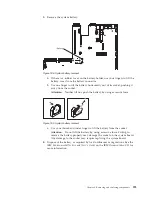


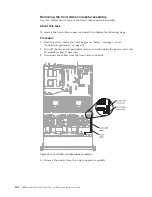


The following notes describe additional information when you install the cable:
v
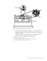
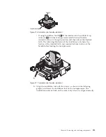
To connect the operator information panel cable on the system board, press
evenly on the cable. Pressing on one side of the cable might cause damage to
the cable or connector.
v
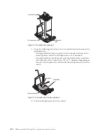
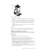
The operator information panel cable must pass through the chassis latch
between fan 3 and fan 4 in order not to impede the fan cage.
6.
Replace the cover (see “Replacing the cover” on page 209).
7.
Slide the server into the rack.
8.
Reconnect the power cords and any cables that you removed.
9.
Turn on the peripheral devices and the server.
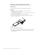
Figure 212. Operator information panel cable connection
Chapter 6. Removing and replacing components
309
Содержание Redboks System x3550 M4
Страница 1: ...IBM System x3550 M4 Type 7914 Installation and Service Guide ...
Страница 2: ......
Страница 3: ...IBM System x3550 M4 Type 7914 Installation and Service Guide ...
Страница 8: ...vi IBM System x3550 M4 Type 7914 Installation and Service Guide ...
Страница 18: ...xvi IBM System x3550 M4 Type 7914 Installation and Service Guide ...
Страница 42: ...24 IBM System x3550 M4 Type 7914 Installation and Service Guide ...
Страница 118: ...100 IBM System x3550 M4 Type 7914 Installation and Service Guide ...
Страница 214: ...196 IBM System x3550 M4 Type 7914 Installation and Service Guide ...
Страница 352: ...334 IBM System x3550 M4 Type 7914 Installation and Service Guide ...
Страница 702: ...684 IBM System x3550 M4 Type 7914 Installation and Service Guide ...
Страница 798: ...780 IBM System x3550 M4 Type 7914 Installation and Service Guide ...
Страница 802: ...784 IBM System x3550 M4 Type 7914 Installation and Service Guide ...
Страница 811: ...Taiwan Class A compliance statement Notices 793 ...
Страница 812: ...794 IBM System x3550 M4 Type 7914 Installation and Service Guide ...
Страница 818: ...800 IBM System x3550 M4 Type 7914 Installation and Service Guide ...
Страница 819: ......
Страница 820: ... Part Number 00Y8006 Printed in USA 1P P N 00Y8006 ...


