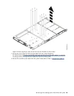


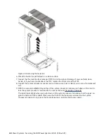

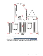
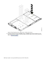

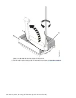


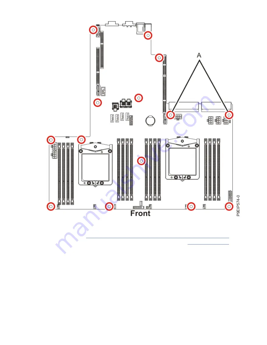
Figure 49. Screw locations
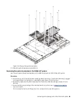
18. Replace the drive signal and drive power cables from the system backplane.
For instructions, see “Replacing the disk drive backplane in the 9006-12P system” on page 17.
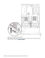
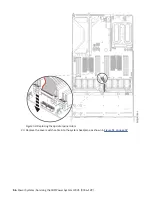
19. Replace the operator panel cable into the system backplane as shown in Figure 50 on page 56.
As you face the front of the system, the red stripe on the cable needs to be on the left side of the
connector.
Removing and replacing parts in the 9006-12P system 55
Содержание Power System LC921 9006-12P
Страница 1: ...Power Systems Servicing the IBM Power System LC921 9006 12P IBM...
Страница 14: ...xiv Power Systems Servicing the IBM Power System LC921 9006 12P...
Страница 20: ...Figure 3 Turning the 2 5 inch tray upside down 6 Power Systems Servicing the IBM Power System LC921 9006 12P...
Страница 23: ...Figure 6 Turning the 2 5 inch tray upside down Removing and replacing parts in the 9006 12P system 9...
Страница 118: ...104 Power Systems Servicing the IBM Power System LC921 9006 12P...
Страница 120: ...106 Power Systems Servicing the IBM Power System LC921 9006 12P...
Страница 131: ......
Страница 132: ...IBM...


