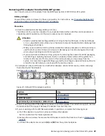

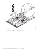

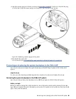


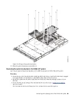

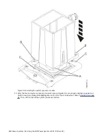

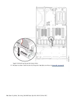
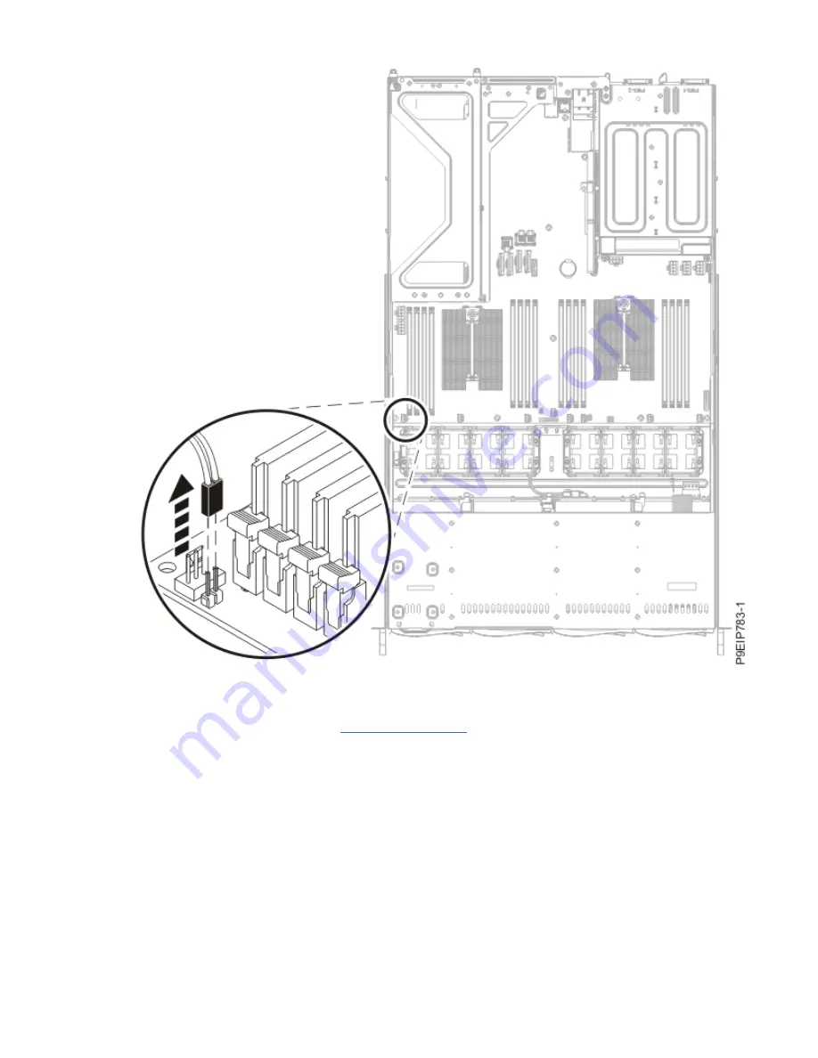
Figure 37. Removing the cover switch cable
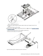
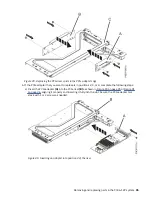
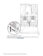
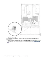
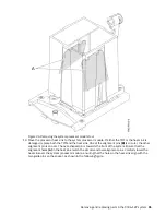
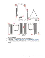
10. Remove the 14 screws from the system backplane.
The screw locations are shown in Figure 38 on page 44.
Removing and replacing parts in the 9006-12P system 43
Содержание Power System LC921 9006-12P
Страница 1: ...Power Systems Servicing the IBM Power System LC921 9006 12P IBM...
Страница 14: ...xiv Power Systems Servicing the IBM Power System LC921 9006 12P...
Страница 20: ...Figure 3 Turning the 2 5 inch tray upside down 6 Power Systems Servicing the IBM Power System LC921 9006 12P...
Страница 23: ...Figure 6 Turning the 2 5 inch tray upside down Removing and replacing parts in the 9006 12P system 9...
Страница 118: ...104 Power Systems Servicing the IBM Power System LC921 9006 12P...
Страница 120: ...106 Power Systems Servicing the IBM Power System LC921 9006 12P...
Страница 131: ......
Страница 132: ...IBM...


