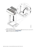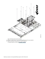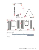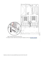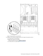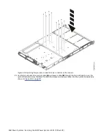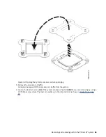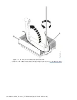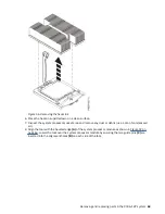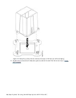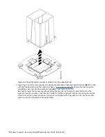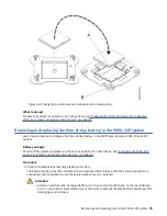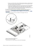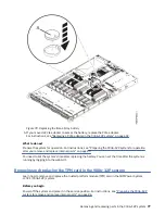
Figure 56. Removing the heat sink
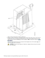
6. Place the heat sink upside down on a clean surface.
7. Inspect the system processor socket area and remove any dust or debris (use a can of compressed
air).
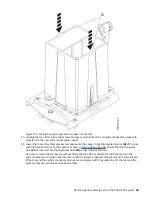
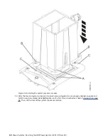
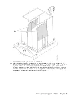
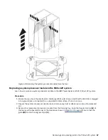
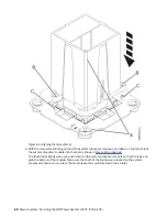
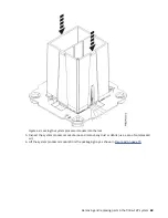
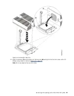
8. Align the tool with the beveled edge (A) of the system processor module as shown in Figure 57 on
page 64. Lower the tool over the system processor module by ensuring the two guide pins (C) are
inserted into the alignment holes (B) on each side of the tool.
Removing and replacing parts in the 9006-12P system 63
Содержание Power System LC921 9006-12P
Страница 1: ...Power Systems Servicing the IBM Power System LC921 9006 12P IBM...
Страница 14: ...xiv Power Systems Servicing the IBM Power System LC921 9006 12P...
Страница 20: ...Figure 3 Turning the 2 5 inch tray upside down 6 Power Systems Servicing the IBM Power System LC921 9006 12P...
Страница 23: ...Figure 6 Turning the 2 5 inch tray upside down Removing and replacing parts in the 9006 12P system 9...
Страница 118: ...104 Power Systems Servicing the IBM Power System LC921 9006 12P...
Страница 120: ...106 Power Systems Servicing the IBM Power System LC921 9006 12P...
Страница 131: ......
Страница 132: ...IBM...

