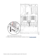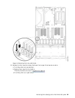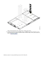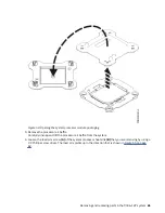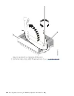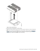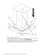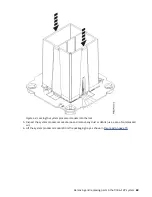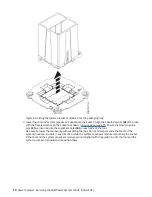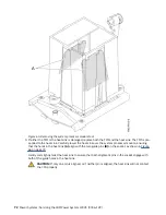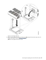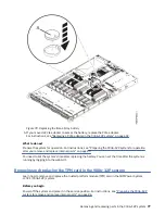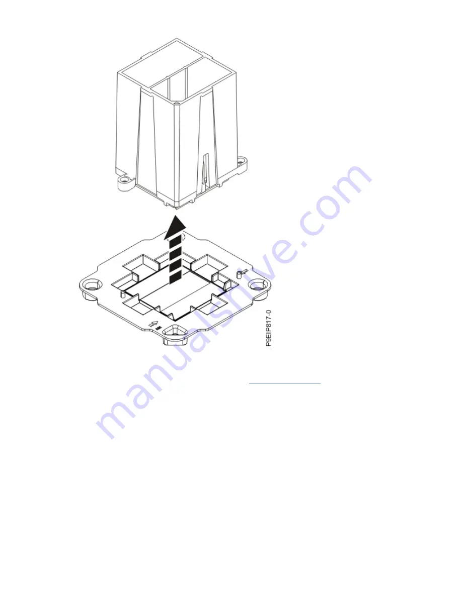
Figure 63. Lifting the system processor module from the packaging tray
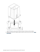
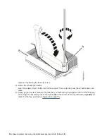
7. Lower the tool and system processor module onto the socket. Align the beveled corner (A) of the tool
with the beveled corner on the socket as shown in Figure 64 on page 71. Ensure that the two guide
pins (C) are inserted into the alignment holes (B) on each side of the tool.
Use care to lower the tool evenly without tilting the tool. Do not attempt to slide the tool and the
system processor module in any direction while the system processor module is touching the socket.
If the tool and the system processor module are not aligned with the guide pins, lift the tool and the
system processor module and reposition them.
70 Power Systems: Servicing the IBM Power System LC921 (9006-12P)
Содержание Power System LC921 9006-12P
Страница 1: ...Power Systems Servicing the IBM Power System LC921 9006 12P IBM...
Страница 14: ...xiv Power Systems Servicing the IBM Power System LC921 9006 12P...
Страница 20: ...Figure 3 Turning the 2 5 inch tray upside down 6 Power Systems Servicing the IBM Power System LC921 9006 12P...
Страница 23: ...Figure 6 Turning the 2 5 inch tray upside down Removing and replacing parts in the 9006 12P system 9...
Страница 118: ...104 Power Systems Servicing the IBM Power System LC921 9006 12P...
Страница 120: ...106 Power Systems Servicing the IBM Power System LC921 9006 12P...
Страница 131: ......
Страница 132: ...IBM...

