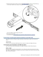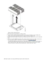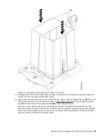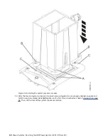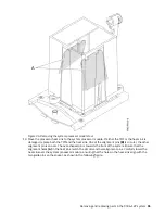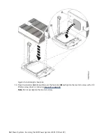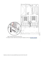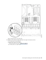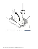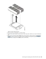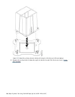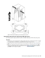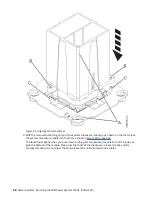
Figure 47. Tightening the load arm screw
The following steps continue installing components into the new system backplane:
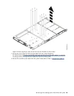
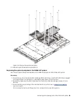
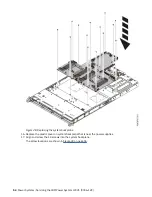
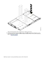
15. Holding the processor heat sink, carefully lower the system backplane into the chassis, then slide it
slightly back.
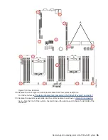
See Figure 48 on page 54.
Removing and replacing parts in the 9006-12P system 53
Содержание Power System LC921 9006-12P
Страница 1: ...Power Systems Servicing the IBM Power System LC921 9006 12P IBM...
Страница 14: ...xiv Power Systems Servicing the IBM Power System LC921 9006 12P...
Страница 20: ...Figure 3 Turning the 2 5 inch tray upside down 6 Power Systems Servicing the IBM Power System LC921 9006 12P...
Страница 23: ...Figure 6 Turning the 2 5 inch tray upside down Removing and replacing parts in the 9006 12P system 9...
Страница 118: ...104 Power Systems Servicing the IBM Power System LC921 9006 12P...
Страница 120: ...106 Power Systems Servicing the IBM Power System LC921 9006 12P...
Страница 131: ......
Страница 132: ...IBM...

