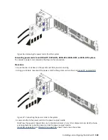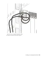
Installing the front cover on an 8335-GTC, 8335-GTG, 8335-GTH, 8335-GTW, or 8335-GTX system
To replace the front cover, complete the steps in this procedure.
Procedure
1. Ensure that you have the electrostatic discharge (ESD) wrist strap on and that the ESD clip is plugged
into a ground jack or connected to an unpainted metal surface. If not, do so now.
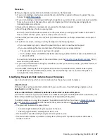
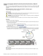
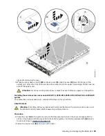
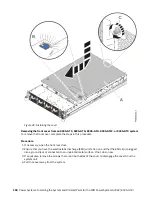
2. Position the cover on the front of the system unit so that the pins on the system match the holes at the
rear of the cover.
3. Press the cover on to the system unit such that the pins engage with the holes and the cover is firmly
seated in place.
4. If applicable, replace the screws on each side of the cover to secure the system to the rack.
5. Close the front rack door.
Service and operating positions for the 8335-GTC, 8335-GTG, 8335-GTH, 8335-GTW, or
8335-GTX system
Learn how to place on an IBM Power System AC922 (8335-GTC, 8335-GTG, and 8335-GTH) or IBM
Power System AC922 (8335-GTW and 8335-GTX) system into the service or operating position.
Placing an 8335-GTC, 8335-GTG, 8335-GTH, 8335-GTW, or 8335-GTX system into the service
position
To place a system into the service position, complete the steps in this procedure.
About this task
Pick the proper type of rails for your system:
• “Slide rails” on page 101
• “Fixed rails” on page 102
Slide rails
Use this procedure when your system is installed using slide rails.
Before you begin
Notes:
• When you place the system into the service position, you must ensure that all stability plates are firmly
installed to prevent the rack from toppling. Ensure that only one system unit is in the service position at
a time.
• Ensure that the cables at the rear of the system unit do not catch or bind as you pull the system unit
forward in the rack.
• When the slide rails are fully extended, the rail safety latches lock into place. This action prevents the
system from being pulled out too far.
Procedure
1. Remove the screws on either side of the system that secure the system to the rack.
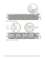
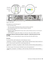
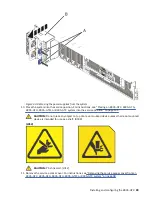
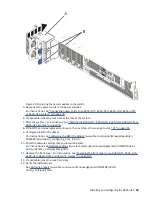
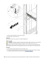
2. Push down the front latches (A) that secure the system unit to the rack.
Installing and configuring the 8335-GTX 101
Содержание Power System AC922
Страница 1: ...Power Systems Installing the System and Ordered Parts for the IBM Power System AC922 8335 GTX IBM...
Страница 4: ...iv...
Страница 14: ...xiv Power Systems Installing the System and Ordered Parts for the IBM Power System AC922 8335 GTX...
Страница 105: ...or or or or Installing and configuring the 8335 GTX 91...
Страница 121: ...Figure 54 Routing the power cord loop in the cable management arm Installing and configuring the 8335 GTX 107...
Страница 126: ...112 Power Systems Installing the System and Ordered Parts for the IBM Power System AC922 8335 GTX...
Страница 137: ......
Страница 138: ...IBM...

