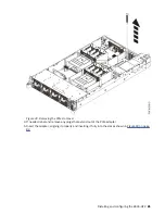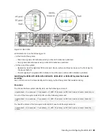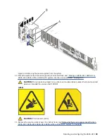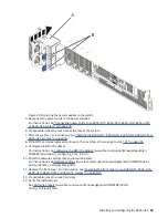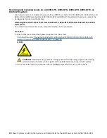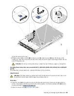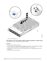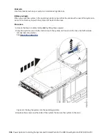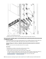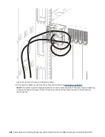
Figure 44. Removing the power supplies from the system
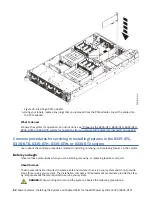
10. Place the system into the service position. For instructions, see “Placing an 8335-GTC, 8335-GTG,
8335-GTH, 8335-GTW, or 8335-GTX system into the service position” on page 101.
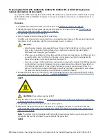
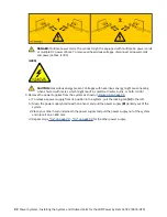
CAUTION: Do not place any object on top of a rack-mounted device unless that rack-mounted
device is intended for use as a shelf. (R008)
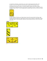
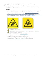
(L012)
CAUTION: Pinch hazard. (L012)
11. Remove the service access cover. For instructions, see “Removing the service access cover from an
8335-GTC, 8335-GTG, 8335-GTH, 8335-GTW, or 8335-GTX system” on page 98.
Installing and configuring the 8335-GTX 93
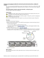
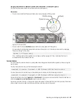
Содержание Power System AC922
Страница 1: ...Power Systems Installing the System and Ordered Parts for the IBM Power System AC922 8335 GTX IBM...
Страница 4: ...iv...
Страница 14: ...xiv Power Systems Installing the System and Ordered Parts for the IBM Power System AC922 8335 GTX...
Страница 105: ...or or or or Installing and configuring the 8335 GTX 91...
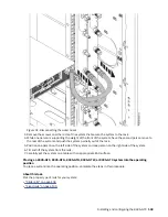
Страница 121: ...Figure 54 Routing the power cord loop in the cable management arm Installing and configuring the 8335 GTX 107...
Страница 126: ...112 Power Systems Installing the System and Ordered Parts for the IBM Power System AC922 8335 GTX...
Страница 137: ......
Страница 138: ...IBM...

