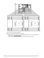
Figure 9. Location of the memory modules
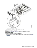
4. Remove all of the memory modules from the system.
a) Unlock each memory module by pushing the locking tabs away from the memory module, in the
direction shown in Figure 10 on page 17.
The lever action of opening the tabs pushes the memory module out of the slot.
16 Power Systems: Installing the System and Ordered Parts for the IBM Power System AC922 (8335-GTX)
Содержание Power System AC922
Страница 1: ...Power Systems Installing the System and Ordered Parts for the IBM Power System AC922 8335 GTX IBM...
Страница 4: ...iv...
Страница 14: ...xiv Power Systems Installing the System and Ordered Parts for the IBM Power System AC922 8335 GTX...
Страница 105: ...or or or or Installing and configuring the 8335 GTX 91...
Страница 121: ...Figure 54 Routing the power cord loop in the cable management arm Installing and configuring the 8335 GTX 107...
Страница 126: ...112 Power Systems Installing the System and Ordered Parts for the IBM Power System AC922 8335 GTX...
Страница 137: ......
Страница 138: ...IBM...

