background image


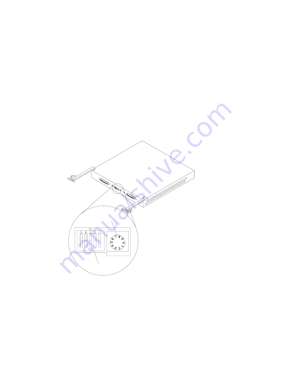
Set the Expansion Unit Interface Options

There is a set of option switches located on the back of the
expansion unit. You can use these switches to select interface
options. Drive SCSI IDs identify each drive in the expansion unit.

Option Switches

Tray Number Switch

Switches 2 through 5 are Reserved. Leave these switches in the OFF
(or down) position.

Your expansion unit supports up to two external SCSI buses and up
to two internal SCSI buses. When the expansion unit is configured
to have all 10 disk drives in a single SCSI bus, either external cable
connector can be used. This configuration is the default state (OFF
or down) of Switch 1. See “Drive Numbering” on page 39 for
detailed information on matching SCSI IDs to drive bay positions.


Chapter  2. Installation Setup

21

Содержание EXP15

Страница 1: ...IBM Netfinity EXP15 Installation and User s Handbook...

Страница 2: ......

Страница 3: ...IBM Netfinity EXP15 Installation and User s Handbook IBM...

Страница 4: ...s described in this publication at any time This publication was developed for products and services offered in the United States of America and the United Kingdom It is possible that this publicatio...

Страница 5: ...enska xvi About This Book xxi How This Book is Organized xxi Notices Used in This Book xxii Related Publications xxii Welcome and Thank You xxiii Chapter 1 Introduction 1 Features at a Glance 3 Front...

Страница 6: ...ng Problems 59 Overview of Problem Causes 59 Troubleshooting Charts 60 Chapter 6 Getting Help Service and Information 63 Service Support 63 Before You Call for Service 65 Getting Customer Support and...

Страница 7: ...ments before performing any of the instructions Instru es de Cuidado e Perigo Portugu s do Brasil Importante Todas as instru es de cuidado e perigo deste manual s o iniciadas por um n mero Este n mero...

Страница 8: ...vi IBM Netfinity EXP15 Installation and User s Handbook...

Страница 9: ...ve p e etli v echny bezpe nostn instrukce Sikkerhedsforskrifter m rket Pas p og Fare dansk Vigtigt Alle sikkerhedsforskrifter i dette h fte begynder med et tal Dette tal bruges som krydshenvisning fra...

Страница 10: ...gnes Attention et Danger Fran ais Important Toutes les consignes Attention et Danger indiqu es dans ce document sont pr c d es d un num ro Ce dernier permet de mettre en correspondance la consigne en...

Страница 11: ...etzten Versionen dieses Hinweises die in der Brosch re mit den Sicherheitshinweisen Safety Information enthalten sind Wenn z B ein Sicherheitshinweis mit der Nummer 1 beginnt so erscheint die bersetzu...

Страница 12: ...versioni tradotte che sono riportate nella nelle informazioni di sicurezza Safety information Ad esempio se un avviso di attenzione inizia con il numero 1 la corrispondente versione tradotta riportata...

Страница 13: ...Safety Information xi...

Страница 14: ...en alle vertalingen in dit boekje Safety Information Als een instructie bijvoorbeeld begint met nummer 1 kunt u de Engelse versie en alle vertalingen in dit boekje Safety Information eveneens vinden...

Страница 15: ...faremerknad og den oversatte versjonen av merknaden som du kan finne i boken om sikkerhetsinformasjon Safety Information Hvis for eksempel en advarselsmerknad begynner med nummeret 1 finner du overset...

Страница 16: ...ncontrada no manual Safety Information Informa es sobre Seguran a Por exemplo se uma nota de cuidado come a pelo n mero 1 a respectiva tradu o apresentada no manual Safety Information identificada com...

Страница 17: ...zodpovedaj ceho prekladu anglickej bezpe nostnej in trukcie v kni ke Safety Information Nap klad ak bezpe nostn in trukcie za naj slom 1 n jdete zodpovedaj ci perklad v kni keSafety Information pod sl...

Страница 18: ...ducciones de esta declaraci n de precauci n aparecen en el manual Informaci n de seguridad Safety Information bajo Declaraci n 1 Lea atentamente todas las declaraciones de precauci n y peligro antes d...

Страница 19: ...Safety Information xvii...

Страница 20: ...e attached must also be connected to properly wired receptacles When possible use one hand to connect or disconnect signal cables to prevent a possible shock from touching two surfaces with different...

Страница 21: ...urn device ON To Disconnect 1 Turn Everything OFF 2 First remove power cord s from outlet 3 Remove signal cables from receptacles 4 Remove all cables from devices NOTE In the UK by law the telephone c...

Страница 22: ...xx IBM Netfinity EXP15 Installation and User s Handbook...

Страница 23: ...rver rack Chapter 4 Installing and Replacing Devices contains step by step instructions for installing and removing options such as internal drives and customer replaceable units CRUs In addition this...

Страница 24: ...that can be potentially hazardous to you A caution notice is placed just before descriptions of potentially hazardous procedure steps or situations Related Publications Additional publications are av...

Страница 25: ...enhances IBM s support for setup installation configuration and problem determination It provides assistance for popular network operating systems and network adapters from IBM and non IBM vendors In...

Страница 26: ...Welcome and Thank You xxiv IBM Netfinity EXP15 Installation and User s Handbook...

Страница 27: ...both low voltage differential LVD and single ended SE host SCSI interfaces The drive interface is single ended SE Designed for easy installation and integration into a wide range of system environmen...

Страница 28: ...trols 5 Power Supply Controls Indicators and Connectors 7 Fan Controls and Indicators 8 Expansion Bays 9 System Management Software Support 11 Getting Help on the World Wide Web 12 IBM Start Up Suppor...

Страница 29: ...together ESM Board Technology and Interfaces Model SCSI LVD single ended SCSI bus interface Two 68 pin VHDCI connectors for incoming and outgoing SCSI bus cables Note For a list of the operating speci...

Страница 30: ...ocated on the front panel above the drive bays Activity LEDs These ten green lights found on the left side of each pair of lights indicate drive activity when flashing Power Fault LEDs The power fault...

Страница 31: ...er controls indicators and connectors ESM Board User Controls SCSI Bus 1 Connector SCSI Bus 2 Connector Lever Option Switches Tray Number Switch Term Power LED Term Power LED ESM Board FRU Lever Over...

Страница 32: ...f termination term power is present When the term power is present indicator is on it indicates that the other end of the cable is connected to a powered on controller Each external bus has a separate...

Страница 33: ...e green LEDs are on when the power switches are turned on Fault LEDs These amber LEDs are on after a power supply failure or if one power supply is turned on and the other power supply is turned off P...

Страница 34: ...fans in your expansion unit pull in fresh air and force out hot air These fans are hot swap redundant however when one fan fails the fan unit needs to be replaced within 48 hours in order to maintain...

Страница 35: ...ys in your expansion unit For information on installing and replacing devices in these bays refer to Chapter 4 Installing and Replacing Devices on page 35 Hot Swap Drive Bays Hot Swap Drive Bays The e...

Страница 36: ...fan fails the second fan continues to operate Each unit contains two fans ESM Board Bay The environmental services monitor ESM board provides a SCSI interface to the drives and monitors the overall st...

Страница 37: ...ersion 5 1 2 or later for more information on setting up system management software This system management software is supported on the IBM ServeRAID Adapter with Service Pack version 2 23 or later Sy...

Страница 38: ...your first 90 days after installation Assistance is available for IBM and non IBM network operating systems network interface adapters and other optional peripherals For more information about this e...

Страница 39: ...ss This chapter contains Preparatory Tasks and Assumptions 14 Inventory Checklist 15 Preparing the Rack 16 Power Cord Routing Information 16 Support Rail Installation Information 16 Preparing the Expa...

Страница 40: ...have already installed the other components in the rack and moved the rack near its permanent operating location You have already installed and configured the host controllers and appropriate host ada...

Страница 41: ...torage Expansion Unit Power cords 2 Rack mounting hardware kit 1 Two rails right and left assembly Eight black M6 screws Publications IBM Netfinity EXP15 Installation and User s Handbook IBM Safety Bo...

Страница 42: ...nal power unit consider connecting and routing the expansion unit power cords in the cabinet before you install the expansion unit Support Rail Installation Information To install the expansion unit i...

Страница 43: ...s shipped with two identical power cords 4 Line up the mounting hardware in the rack to verify its placement Note Make sure that there is enough open space above the mounting hardware to accommodate t...

Страница 44: ...he power cords so that they are easily accessible to the rear of the expansion unit once it is installed 8 Unplug the cables and power cords from the electrical outlets but keep them routed in the rac...

Страница 45: ...e all the CRUs you can reduce the overall weight For information about removing CRUs go to Chapter 4 Installing and Replacing Devices on page 35 The following are CRUs in your expansion unit Up to ten...

Страница 46: ...Movement can cause static electricity to build up around you Always handle components carefully Never touch any exposed circuitry Prevent others from touching components When you are installing a new...

Страница 47: ...5 are Reserved Leave these switches in the OFF or down position Your expansion unit supports up to two external SCSI buses and up to two internal SCSI buses When the expansion unit is configured to ha...

Страница 48: ...External SCSI bus 1 maps to internal SCSI bus 1 and external SCSI bus 2 maps to internal SCSI bus 2 The five disk drives of internal SCSI bus 1 have the SCSI addresses of 0 4 and the five disk drives...

Страница 49: ...ips screwdriver Note Some of the installation procedures require three people Review the safety and handling guidelines specified under Safety Information on page v These guidelines will help you work...

Страница 50: ...3000 ft expansion unit on 10 to 32 C 50 to 90 F Altitude 914 m 3000 ft to 2133 m 7000 ft Humidity 10 to 80 Acoustical Noise Emissions Values For open bay 0 drives installed and typical system configu...

Страница 51: ...n on preparing the rack In this section you will use the right and left rail assembly brackets and eight black hex head screws provided with your hardware kit 5 CAUTION Use safe lifting practices when...

Страница 52: ...sion unit into a rack with square or round mounting holes 1 From the rear of the rack locate the desired position on the rack based on the even EIA U level space U U U Level U Rail Assembly Bracket U...

Страница 53: ...ly tighten the screws Rear of Rack 3 Loosen the five screws four large screws and one small screw 2 located on the interior of the rail assembly then slide the front rail assembly forward 3 until it m...

Страница 54: ...e screws on the rear of the rack and the four interior screws on the rail assembly 6 Repeat the rail assembly procedure on the opposite side of the rack 7 Remove the two small 6 32 screws 1 on the int...

Страница 55: ...Installing the Expansion Unit in a Rack 8 Slide the expansion unit into the rack Front of Rack Chapter 3 Rack Installation 29...

Страница 56: ...the bezel to the front of the expansion unit The decorative bezel is mounted correctly when the alignment pins match with the holes in the expansion unit Front of Rack c Insert the remaining two black...

Страница 57: ...stalling the CRUs into the expansion unit 12 Connect the power cord to the rear of each power supply Remove the nut and wrap the clamp around the power cord approximately eight inches from the end Rea...

Страница 58: ...Sensitive Devices on page 20 Turn off both power supply switches on the rear of your expansion unit Follow any additional installation and safety instructions that come with the rack 5 CAUTION Use saf...

Страница 59: ...with Hot Swap Power Supplies on page 49 2 Remove the fan see Replacing a Hot Swap Fan on page 53 3 Remove the two 6 32 screws 1 from the rear of the expansion unit 4 Remove the drives Be sure to labe...

Страница 60: ...ention Do not remove the bottom black hex head screws These secure the rails that support your expansion unit Front of Rack 6 Remove the bezel 1 Attention When handling the expansion unit avoid touchi...

Страница 61: ...k Drives 37 Drive Numbering 39 Installing Hot Swap Drives 41 Installing Additional Hot Swap Drives 42 Replacing Internal Hot Swap Drives 45 Working with SCSI Components 47 SCSI Configurations 47 Cable...

Страница 62: ...your expansion unit Back up all important data before you make changes to storage devices such as hard disk drives If you are installing the expansion unit in a rack be sure that the rack provides ade...

Страница 63: ...hard disk drive without turning off the expansion unit Therefore you have the advantage of continuing to operate your system while a hard disk drive is removed or installed These drives are known as...

Страница 64: ...tions Activity LED Green Flashes during read write or inquiry operations to the drive Power Fault LED Green On when a drive is present Power Fault LED Amber Green Green and amber flashes to indicate a...

Страница 65: ...e Use the option switch on the ESM board to change the ID settings 1 0 2 0 1 1 2 1 1 2 2 2 1 3 2 3 1 4 2 4 The first number represents the channel number and the second is the SCSI ID Important inform...

Страница 66: ...o channels are daisy chained using option switch 1 in the off position then the SCSI IDs are as shown and the drives are all on the same channel 1 0 1 8 1 1 1 9 1 2 1 10 1 3 1 11 1 4 1 12 40 IBM Netfi...

Страница 67: ...ntain blank drive trays in the unused drive bays Before installing new drives you must remove the blank trays which should be saved for future use Each of the ten bays must always contain either a bla...

Страница 68: ...is powered up and running Before you begin Read Handling Static Sensitive Devices on page 20 Read the instructions that come with the internal drive Handle the drive tray assembly carefully 1 Check f...

Страница 69: ...open the drive lever 2 b Label the drive 3 according to the instructions in Drive Numbering on page 39 c Slide the drive into the empty bay d Make sure the hooks 4 on the top edge of the drive lever 2...

Страница 70: ...cases the drive will automatically reset to either a hot spare HSP or be rebuilt ONL See the ServeRAID II User s Guide for additional information If the state change in the ServeRAID II configuration...

Страница 71: ...es or types within an array Before you begin Read Handling Static Sensitive Devices on page 20 Be sure to handle the drives carefully Determine the location of the drive that you want to remove 1 Remo...

Страница 72: ...on The amber LED should go off within 10 seconds of the drive state change to something other than DDD If your SCSI adapter is the IBM ServeRAID II in some cases the drive will automatically reset to...

Страница 73: ...the SCSI bus 1 connector 2 Attach a second external SCSI cable from the controller in the server to the SCSI bus 2 connector 3 Set Switch 1 to the ON or up position To configure the expansion unit as...

Страница 74: ...of cable to operate at Fast SCSI speeds 10 MHz or 20 MB sec The speed setting is a setup operation for a SCSI controller Refer to your SCSI controller documentation to set the appropriate speed Note A...

Страница 75: ...Attention Always follow these instructions when installing or removing a hot swap power supply To remove a hot swap power supply 1 Turn the power supply switch to the OFF position 2 Unplug the power s...

Страница 76: ...ed on the side of the supply that faces the middle of the machine If not remove the lever screw flip the lever over and tighten the screw on the opposite side 1 Ensure that the ac power switch on the...

Страница 77: ...he power cord to the power supply AC Power Switches 6 Plug the supply power cord into a properly grounded electrical outlet The amber LED stays on when the power switch is turned off 7 Turn the power...

Страница 78: ...only to the total time that a fan is out of the expansion unit beginning when you remove the failed unit and ending when you reseat the new one This does not include the time it takes you to perform...

Страница 79: ...Place the fan CRU in front of the fan slot b Hold the latch open and slide the fan all the way into the slot If the fan does not go into the bay rotate it The latch should always be on the side close...

Страница 80: ...ower for the initial start up of the expansion unit 1 Verify that a All communication and power cables are plugged into the back of the expansion unit and an ac power outlet b All hard disk drives are...

Страница 81: ...ber and green LEDs on the expansion unit turn on and off intermittently When the power up sequence is complete only the green LEDs should remain on If you still have one or more amber LEDs on refer to...

Страница 82: ...ff the power only when Instructions in a hardware or software procedure require you to turn off the power A factory representative or service technician tells you to turn off the power A power outage...

Страница 83: ...ue to electrical surges when power is restored If the expansion unit loses power unexpectedly it might be due to a hardware failure in the power system or midplane see Table 2 on page 60 Use this proc...

Страница 84: ...eck the expansion unit for damage Note If there is no visible damage continue with Step 2 otherwise have your system serviced See Chapter 6 Getting Help Service and Information on page 63 2 After you...

Страница 85: ...is chapter contains Overview of Problem Causes 59 Troubleshooting Charts 60 Overview of Problem Causes System problems can be caused by hardware software or user error An example of a user error is pr...

Страница 86: ...and green LEDs on Power supply CRU Power supply failure Replace failed power supply CRU Amber green LEDs off Drive CRU CRU not plugged in Make sure that the drive is inserted and locked in place corre...

Страница 87: ...Power cord unplugged or switch turned off Make sure the cord is plugged in and the switch is turned on Power supply CRU unplugged Turn off the power switch Make sure the power supply is plugged in pro...

Страница 88: ...ard replaced service technician only SCSI bus Cable too long If the external SCSI controller is SE check LEDs make sure the cable length is appropriate Random errors Subsystem Midplane failure Have th...

Страница 89: ...S http www pc ibm com us intellistation IBM IntelliStation U S http www pc ibm com us netfinity IBM Netfinity and PC Servers U S http www pc ibm com us options IBM Options U S You can select a countr...

Страница 90: ...available that apply to your hardware Be sure to retain your proof of purchase to obtain warranty service Please have the following information ready when you call Machine Type and Model Serial number...

Страница 91: ...POST error message charts in your hardware documentation If you do not receive a POST error code but suspect a hardware problem refer to the troubleshooting information in your hardware documentation...

Страница 92: ...517 0001 In Canada In Montreal call 514 938 3022 In Toronto call 905 316 4255 or 416 956 7877 In Vancouver call 604 664 6464 In the U K call 01256 336655 Commercial online services that contain inform...

Страница 93: ...henever new information becomes available about your registered products You also can access online support forums which are community sites monitored by IBM support staff For information about specif...

Страница 94: ...There might be a charge for this service depending on the request For more information about configuring your PC for Online Housecall In the U S call 1 800 772 2227 In Canada call 1 800 565 3344 In a...

Страница 95: ...problem Exact wording of any error messages Hardware and software configuration information for your system If possible be at your computer when you call In the U S and Canada these services are avail...

Страница 96: ...zerland French Suisse 022 310 0418 Switzerland Italian Svizzera 091 971 0523 United Kingdom United Kingdom 01475 555555 U S A and Puerto Rico U S A and Puerto Rico 1 800 772 2227 Getting Help Around t...

Страница 97: ...PC Support Line Enhanced PC Support is available for desktop and mobile IBM computers that are not connected to a network Technical support is provided for IBM computers and IBM or non IBM options ope...

Страница 98: ...In addition many popular non IBM adapters and network interface cards are supported This service includes all of the features of the Enhanced PC Support Line plus Installing and configuring client wor...

Страница 99: ...the U S include Carry in service to on site service If your warranty provides carry in repair service you can upgrade to on site repair service either standard or premium The standard upgrade provides...

Страница 100: ...eseller or IBM marketing representative Ordering Publications Additional publications are available for purchase from IBM For a list of publications available in your country In the U S Canada and Pue...

Страница 101: ...located on bottom surface on the rear of the machines Product Name IBM Netfinity EXP15 Machine Type 3520 Model Number Serial Number Installed Device Records Use the following tables to keep a record...

Страница 102: ...ocation Disk Drive Part Number and Model Number Disk Drive Serial Number Expansion Unit SCSI Channel 1 2 SCSI Address 0 4 or 8 12 Adapter Number Adapter Channel Number 1 6 Bay 1 Bay 2 Bay 3 Bay 4 Bay...

Страница 103: ...Warranty Statements 78 United States Canada and Puerto Rico 78 United Kingdom 81 Notices 85 Year 2000 Readiness and Instructions 85 Trademarks 87 Industry Canada Class A Emission Compliance Statement...

Страница 104: ...new parts or new and used parts In some cases the Machine may not be new and may have been previously installed Regardless of the Machine s production status IBM s warranty terms apply The IBM Warrant...

Страница 105: ...tore a Machine to good working order When a type of service involves the exchange of a Machine or part the item IBM or your reseller replaces becomes its property and the replacement becomes yours You...

Страница 106: ...r other liability you are entitled to recover damages from IBM In each such instance regardless of the basis on which you are entitled to claim damages from IBM including fundamental breach negligence...

Страница 107: ...y does not cover the repair of damage to the product resulting from Accident disaster misuse and abuse Use of parts not manufactured or sold by IBM Modification of the product Service provided by anyo...

Страница 108: ...vice entitlement which is delivered on the customers premises on site If the product you have purchased carries with it an entitlement to IBM on site service this service is provided during the warran...

Страница 109: ...resellers upon registering with IBM International Warranty Service Office IBM International Warranty Service is provided subject to the terms and conditions of the IBM Warranty Statement provided wit...

Страница 110: ...are installed in or connected to an IBM System Unit which is registered for International Warranty Service 2 Customers are not required to register their machine for International Warranty Service if...

Страница 111: ...e furnishing of this document does not give you any license to these patents You can send license inquiries in writing to IBM Director of Licensing IBM Corporation North Castle Drive Armonk NY 10504 1...

Страница 112: ...ity for the readiness of that software You should contact the software developers directly if you wish to verify readiness understand limitations or look for any software updates To learn more about I...

Страница 113: ...he United States or other countries or both HelpWare IBM Netfinity OS 2 PowerPC ThinkPad ValuePoint Windows registered trademark of Microsoft Corporation Other company product and service names may be...

Страница 114: ...unded cables and connectors must be used in order to meet FCC emission limits IBM is not responsible for any radio or television interference caused by using other than recommended cables and connecto...

Страница 115: ...compatibility A declaration of Conformity with the requirements of the Directive has been signed by IBM United Kingdom Limited PO BOX 30 Spango Valley Greenock Scotland PA160AH Attention This is a Cla...

Страница 116: ...JT three conductor cord a maximum of 15 feet in length and a parallel blade grounding type attachment plug rated 15 amperes 125 volts For units intended to be operated at 230 volts U S use Use a UL li...

Страница 117: ...yria Togo Tunisia Turkey former USSR Vietnam former Yugoslavia Zaire Zimbabwe 13F9997 Denmark 14F0015 Bangladesh Burma Pakistan South Africa Sri Lanka 14F0033 Antigua Bahrain Brunei Channel Islands Cy...

Страница 118: ...92 IBM Netfinity EXP15 Installation and User s Handbook...

Страница 119: ...dling static sensitive devices 20 caution continued statements description v checklist 15 clustering 3 CompuServe 66 connecting cables v internal drives 37 connectors device records 75 controls and in...

Страница 120: ...75 records 75 fee services 71 front controls 4 G general information installing drives 42 getting help and service 12 H handling static sensitive devices 20 hard disk drive hot swap 37 installing 42 r...

Страница 121: ...19 multilingual safety information v N network operating systems compatibility 12 network and server startup support 69 network and server support services fee 72 notices product 77 safety information...

Страница 122: ...scription v electrical v general information 36 safety requirements continued handling static sensitive devices 20 SCSI small computer system interface terminators 47 SCSI bus connectors 5 SCSI compon...

Страница 123: ...lications xxii temperature of expansion unit environment 24 term power LED 6 toll free numbers 12 tools 23 36 top front panel controls 4 trademarks 87 tray number switch 6 troubleshooting how to use 6...

Страница 124: ...IBM Part Number 24L7940 Printed in U S A September 1998 24L794...

Отзывы: