1.
Check
the
system-error
LED
on
the
operator
information
panel
on
the
front
of
the
server.
A
lit
system-error
LED
indicates
that
a
problem
exists.
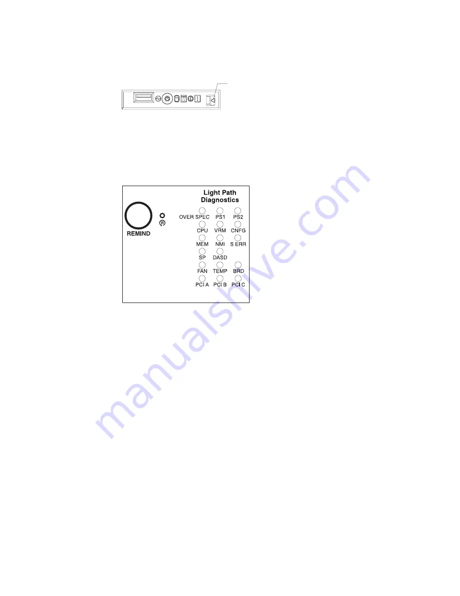
2.
Check
the
light
path
diagnostics
panel.
Press
the
release
latch
on
the
operator
information
panel;
then,
slide
out
the
light
path
diagnostics
panel
to
view
the
lit
LEDs.
These
LEDs
indicate
the
type
of
error
that
has
occurred
and
are
described
in
more
detail
at
“Light
path
diagnostics
errors”
on
page
93.
3.
Once
you
know
the
general
type
of
error
and
the
general
location
of
the
component
involved,
the
next
step
is
to
check
the
system
service
label
on
the
outside
of
the
server.
This
label
gives
an
overview
of
internal
components
that
correspond
to
many
of
the
LEDs
on
the
light
path
diagnostics
panel
and
can
help
to
view
lit
LEDs
inside
the
server.
Note:
Some
of
the
LEDs
on
the
light
path
diagnostics
panel
will
not
have
a
corresponding
LED
lit
on
the
system
board.
For
example:
v
LEDs
for
the
power
supplies
and
hard
disk
drives
are
located
on
or
near
the
individual
power
supply
or
hard
disk
drive.
v
Some
error
conditions
are
corrected
by
taking
an
action
not
related
to
one
particular
component;
see
step
5
on
page
75.
4.
If
the
lit
LED
on
the
light
path
diagnostics
panel
refers
to
a
specific
internal
component
as
indicated
in
step
3,
look
inside
the
server
to
check
the
lit
LEDs
on
the
system
board
(see
Figure
59
on
page
73).
For
example,
a
microprocessor
error
will
light
the
LED
next
to
the
failing
microprocessor.
a.
To
view
LEDs
inside
the
server
without
turning
off
the
server,
read
“Working
inside
the
server
with
the
power
on”
on
page
15;
then,
remove
the
cover
and
look
for
any
lit
error
LEDs.
b.
To
view
LEDs
inside
the
server
without
ac
power
to
the
server,
complete
the
following
steps.
Release latch
Figure
61.
Release
latch
for
light
path
diagnostics
panel
Figure
62.
Light
path
diagnostics
panel
74
xSeries
336
Type
1879
and
Type
8837:
Hardware
Maintenance
Manual
and
Troubleshooting
Guide
Содержание 88371RU
Страница 1: ...xSeries 336 Type 1879 and Type 8837 Hardware Maintenance Manual and Troubleshooting Guide...
Страница 2: ......
Страница 3: ...xSeries 336 Type 1879 and Type 8837 Hardware Maintenance Manual and Troubleshooting Guide...
Страница 15: ...Server on off 8 to 80 Shipment 5 to 100 Chapter 1 General information 5...
Страница 22: ...12 xSeries 336 Type 1879 and Type 8837 Hardware Maintenance Manual and Troubleshooting Guide...
Страница 24: ...14 xSeries 336 Type 1879 and Type 8837 Hardware Maintenance Manual and Troubleshooting Guide...
Страница 92: ...82 xSeries 336 Type 1879 and Type 8837 Hardware Maintenance Manual and Troubleshooting Guide...
Страница 149: ...Appendix B Safety information 139...
Страница 150: ...140 xSeries 336 Type 1879 and Type 8837 Hardware Maintenance Manual and Troubleshooting Guide...
Страница 151: ...Appendix B Safety information 141...
Страница 152: ...142 xSeries 336 Type 1879 and Type 8837 Hardware Maintenance Manual and Troubleshooting Guide...
Страница 153: ...Appendix B Safety information 143...
Страница 154: ...144 xSeries 336 Type 1879 and Type 8837 Hardware Maintenance Manual and Troubleshooting Guide...
Страница 155: ...Appendix B Safety information 145...
Страница 165: ...Appendix B Safety information 155...
Страница 166: ...156 xSeries 336 Type 1879 and Type 8837 Hardware Maintenance Manual and Troubleshooting Guide...
Страница 167: ...Appendix B Safety information 157...
Страница 168: ...158 xSeries 336 Type 1879 and Type 8837 Hardware Maintenance Manual and Troubleshooting Guide...
Страница 172: ...162 xSeries 336 Type 1879 and Type 8837 Hardware Maintenance Manual and Troubleshooting Guide...
Страница 185: ......
Страница 186: ...Part Number 25K8109 1P P N 25K8109...


