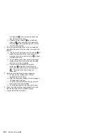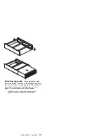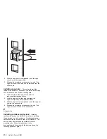
Bays A and B come without a device installed. These
bays are for 5.25-inch, half-high, removable-media
drives, such as tape backup drives. Bays A and B
can be combined into a single full-high bay.
The Netfinity 5500 supports only one diskette drive.
The server does not support hard disk drives in bays
A and B because of cooling considerations.
Note
The server's EMI integrity and cooling are both
protected by having the left front bays
(removable-media bays) covered or occupied.
When you install a drive, save the filler panel
from the bay, in case you later remove the drive
and do not replace it with another.
If you are installing a device with a 50-pin connector
in one of the removable-media bays (bays A–B), you
need a 68-pin to 50-pin converter.
The server supports six slim (1-inch) or three
half-high (1.6-inch), 3.5-inch hot-swap hard disk
drives in the hot-swap bays.
The hot-swap bays connect to a SCSI
backplane.
This backplane is the printed circuit board behind the
bay. The backplane supports up to six hard disk
drives.
The diskette drive uses 1 MB and 2 MB diskettes.
For optimum use, format 1 MB diskettes to 720 KB
and format 2 MB diskettes to 1.44 MB.
SCSI drives:
Some drives have a special design
called
small computer system interface, or SCSI. This
design allows you to attach multiple drives to a single
SCSI channel.
Notes
1. Any information about SCSI drives also applies to
other SCSI devices, such as tape drives.
2. If you plan to install both internal and external
SCSI devices, you must follow the instructions in
“External options” on page 165, in addition to the
instructions in this section.
A 16-bit (wide) SCSI cable connects the hot-swap
backplane to one channel of the integrated RAID SCSI
controller on the system board. An additional 16-bit SCSI
cable with connectors for optional devices in bays A and B
connects to the second channel of the RAID controller.
This cable has a terminator at the other end and is folded
and restrained with a cable clamp to the bottom of the
server between the open bays and the power supply area.
198
Netfinity Server HMM
Содержание 86604RU - Netfinity 5500 - 4RU
Страница 2: ......
Страница 8: ...vi Netfinity Server HMM...
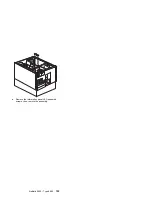
Страница 201: ...a Remove the information panel LED assembly screws then remove the assembly Netfinity 5500 Type 8660 193...
Страница 214: ...1 Hard disk drive 2 Drive tray handle open position 206 Netfinity Server HMM...
Страница 231: ...a Remove the power backplane screws 1 then remove the power backplane Netfinity 5500 Type 8660 223...
Страница 244: ...Screws 236 Netfinity Server HMM...
Страница 247: ...Netfinity 5500 Type 8660 239...
Страница 269: ...a Remove the system board mounting screws then remove the system board Netfinity 5500 Type 8660 261...
Страница 301: ...Parts listing Type 8660 1 2 3 4 5 6 7 8 9 10 11 12 13 14 15 16 17 18 19 20 21 22 23 24 25 Netfinity 5500 Type 8660 293...
Страница 314: ...306 Netfinity Server HMM...
Страница 324: ...316 Netfinity Server HMM...
Страница 325: ...Related service information 317...
Страница 326: ...318 Netfinity Server HMM...
Страница 327: ...Related service information 319...
Страница 340: ...332 Netfinity Server HMM...
Страница 341: ...Related service information 333...
Страница 346: ...338 Netfinity Server HMM...
Страница 402: ...IBM Part Number 00N5902 Printed in U S A S1 L 98 3...

