System board jumpers
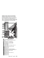
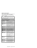
Table 13 describes the jumpers on the system board. The
numbers in the table correspond to the highlighted
numbers on the illustration in “System board component
locations” on page 255.
Note
Turn off the server, and disconnect the power cords
before moving any jumpers.
Table 13. System Board Jumpers
Jumper Name
Description
.8/
J11 Disable
RAID controller
The default position is Enabled (jumper on
pins 1 and 2). Move the the jumper to pins 2
and 3 to disable the RAID controller.
.9/
J45 Reserved
The default position is a jumper on pins 2 and
3.
.1ð/
J32 Power on
control
The default position is normal operation
(jumper on pins 1 and 2). Moving the jumper
to pins 2 and 3 allows the power supply to be
turned on without a control panel or system
management processor.
.11/
J25 Reserved
The default position is a jumper on pins 1 and
2.
.12/
J9 Reserved
The default position is a jumper on pins 1 and
2.
.19/
J34 Reserved
The default is no jumper installed on J34.
.2ð/
J29 Reserved
The default is no jumper installed on J29.
.21/
J26 Reserved
The default is a jumper on pins 2 and 3.
.23/
J51 System
reset
In normal operation, there is no jumper on
J51. Installing a jumper on J51 resets the
system logic.
.26/
J24 Power on
password override
Changing the position of this jumper bypasses
the power-on password check if the jumper
has been moved since the server was last
powered on. You do not need to move the
jumper back to the default position after the
password is overridden.
Changing the position of this jumper does not
affect the administrator password check if an
administrator password is set.
.27/
J30 Flash
ROM page swap
The default position is a jumper installed on
pins 2 and 3. Changing the position of this
jumper will change which of the two pages of
Flash ROM is used when the system is
started.
.45/
J5 Disable
Ethernet controller
The default position is Enabled (jumper on
pins 1 and 2). Move the the jumper to pins 2
and 3 to disable the Ethernet controller.
.46/
J14 Disable
video controller
The default position is Enabled (jumper on
pins 1 and 2). Move the the jumper to pins 2
and 3 to disable the video controller.
Netfinity 5500 - Type 8660
257
Содержание 86604RU - Netfinity 5500 - 4RU
Страница 2: ......
Страница 8: ...vi Netfinity Server HMM...
Страница 201: ...a Remove the information panel LED assembly screws then remove the assembly Netfinity 5500 Type 8660 193...
Страница 214: ...1 Hard disk drive 2 Drive tray handle open position 206 Netfinity Server HMM...
Страница 231: ...a Remove the power backplane screws 1 then remove the power backplane Netfinity 5500 Type 8660 223...
Страница 244: ...Screws 236 Netfinity Server HMM...
Страница 247: ...Netfinity 5500 Type 8660 239...
Страница 269: ...a Remove the system board mounting screws then remove the system board Netfinity 5500 Type 8660 261...
Страница 301: ...Parts listing Type 8660 1 2 3 4 5 6 7 8 9 10 11 12 13 14 15 16 17 18 19 20 21 22 23 24 25 Netfinity 5500 Type 8660 293...
Страница 314: ...306 Netfinity Server HMM...
Страница 324: ...316 Netfinity Server HMM...
Страница 325: ...Related service information 317...
Страница 326: ...318 Netfinity Server HMM...
Страница 327: ...Related service information 319...
Страница 340: ...332 Netfinity Server HMM...
Страница 341: ...Related service information 333...
Страница 346: ...338 Netfinity Server HMM...
Страница 402: ...IBM Part Number 00N5902 Printed in U S A S1 L 98 3...

