Microprocessor kit
The server comes with one microprocessor installed on the
processor board. When you install an additional
microprocessor kit, the server can operate as a symmetric
multiprocessing (SMP) server. With SMP, certain
operating systems and application programs can distribute
the processing load between the microprocessors. This
enhances performance for database and point-of-sale
applications, integrated manufacturing solutions, and other
applications.
Before you begin:
Read “Safety information” on page 308.
Thoroughly review the documentation that comes
with the microprocessor, so that you can
determine whether you need to update the server
basic input/output system (BIOS). The latest
level of BIOS for the server is available through
the World Wide Web and the IBM Bulletin Board
System (BBS). See “Online support” on page iv
for the appropriate World Wide Web addresses
and bulletin-board telephone numbers.
Obtain an SMP-capable operating system
(optional). For a list of supported operating
systems, see http://www.ibm.com/pc/us/compat/
on the World Wide Web.
Notes:
1. The illustrations in this section might differ slightly
from the hardware.
2. To avoid damage and ensure proper server operation
when you install a new or additional microprocessor,
use the same speed and voltage as those of the
currently installed microprocessor. Microprocessor
internal and external clock frequencies must be
identical.
3. The microprocessor that is installed in the primary
microprocessor connector is CPU or processor 1. If a
microprocessor is installed in the secondary
microprocessor connector, it is CPU or processor 2.
If the server has only one microprocessor installed,
that microprocessor is installed in the primary
microprocessor connector and is the boot processor.
If the server has two microprocessors installed, the
microprocessor in the secondary microprocessor
connector is the boot processor and the
microprocessor in the primary microprocessor
connector is the application processor.
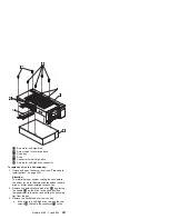
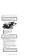
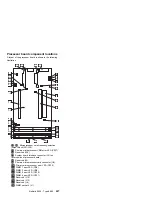
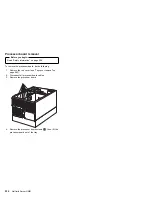
Refer to the following illustration while you perform the
steps in this section.
Netfinity 5500 - Type 8660
217
Содержание 86604RU - Netfinity 5500 - 4RU
Страница 2: ......
Страница 8: ...vi Netfinity Server HMM...
Страница 201: ...a Remove the information panel LED assembly screws then remove the assembly Netfinity 5500 Type 8660 193...
Страница 214: ...1 Hard disk drive 2 Drive tray handle open position 206 Netfinity Server HMM...
Страница 231: ...a Remove the power backplane screws 1 then remove the power backplane Netfinity 5500 Type 8660 223...
Страница 244: ...Screws 236 Netfinity Server HMM...
Страница 247: ...Netfinity 5500 Type 8660 239...
Страница 269: ...a Remove the system board mounting screws then remove the system board Netfinity 5500 Type 8660 261...
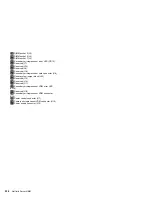
Страница 301: ...Parts listing Type 8660 1 2 3 4 5 6 7 8 9 10 11 12 13 14 15 16 17 18 19 20 21 22 23 24 25 Netfinity 5500 Type 8660 293...
Страница 314: ...306 Netfinity Server HMM...
Страница 324: ...316 Netfinity Server HMM...
Страница 325: ...Related service information 317...
Страница 326: ...318 Netfinity Server HMM...
Страница 327: ...Related service information 319...
Страница 340: ...332 Netfinity Server HMM...
Страница 341: ...Related service information 333...
Страница 346: ...338 Netfinity Server HMM...
Страница 402: ...IBM Part Number 00N5902 Printed in U S A S1 L 98 3...

