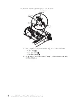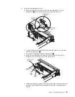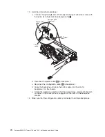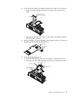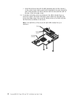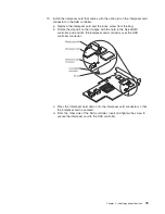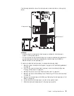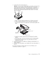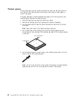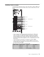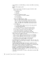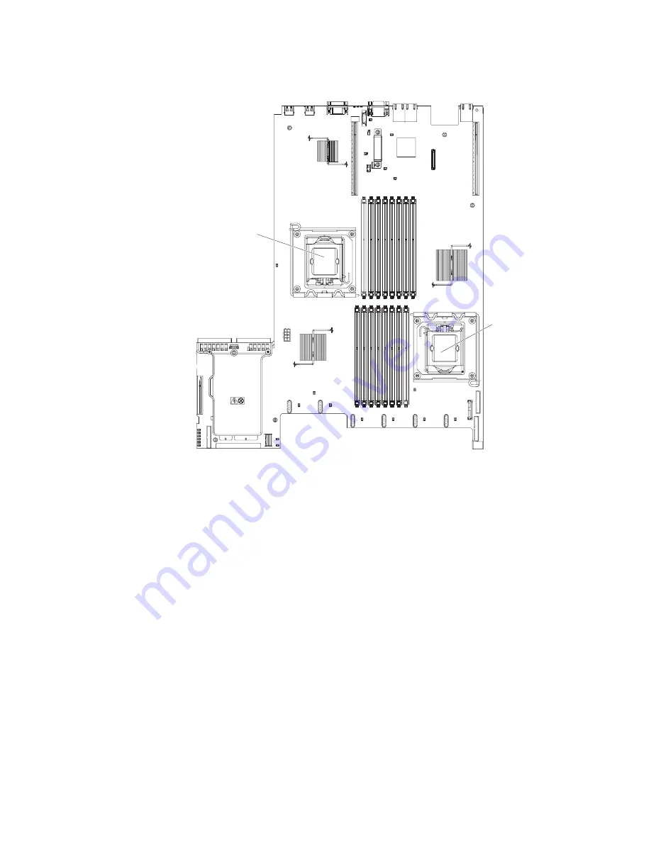
The following illustration shows the microprocessor socket locations on the system
board.
Microprocessor 1
Microprocessor 2
Attention:
v
A startup (boot) microprocessor must always be installed in microprocessor
socket 1 on the system board.
v
To ensure correct server operation when you install an additional microprocessor,
use microprocessors that are compatible and install at least one DIMM in a
DIMM connector for microprocessor 2.
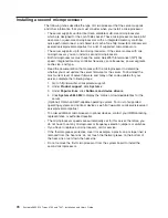
To install an additional microprocessor, complete the following steps:
1. Read the safety information that begins on page vii and “Installation guidelines”
on page 38.
2. Turn off the server and disconnect all power cords and external cables (see
“Turning off the server” on page 22).
3. Remove the server cover (see “Removing the cover” on page 44).
4. Remove PCI riser-card assembly 2 (see “Removing a PCI riser-card assembly”
on page 46).
5. Remove the microprocessor air baffle (see “Removing the microprocessor 2 air
baffle” on page 48).
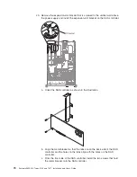
6. Locate the second microprocessor socket on the system board.
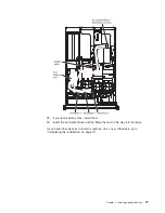
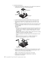
7. Rotate the heat-sink release lever to the fully open position.
Chapter 2. Installing optional devices
79
Содержание 7947E3U
Страница 1: ......
Страница 2: ......
Страница 3: ...System x3650 M2 Types 4199 and 7947 Installation and User s Guide...
Страница 8: ...vi System x3650 M2 Types 4199 and 7947 Installation and User s Guide...
Страница 16: ...xiv System x3650 M2 Types 4199 and 7947 Installation and User s Guide...
Страница 40: ...24 System x3650 M2 Types 4199 and 7947 Installation and User s Guide...
Страница 150: ...134 System x3650 M2 Types 4199 and 7947 Installation and User s Guide...
Страница 162: ...Taiwan Class A compliance statement 146 System x3650 M2 Types 4199 and 7947 Installation and User s Guide...
Страница 168: ...152 System x3650 M2 Types 4199 and 7947 Installation and User s Guide...
Страница 169: ......
Страница 170: ...Part Number 81Y6111 Printed in USA 1P P N 81Y6111...

