background image

Page 9-1 : CTS 330 Owner’s Manual

    Hot Carbonating Truckmount System 

CTS 330

Water and Chemical System

Chemical Flow Operation

The engine, vacuum pump, air compressor, drive system, and heat exchanger are the
primary components of the cleaning system.  The objective of this system is to move
cleaning solution from the solution tank


to the surface in need of cleaning, and

eventually back to the recovery tank.  The first part of this process is to move the
cleaning solution out of the solution tanks.  This is accomplished by pressurizing the
solution tanks with the air compressor.  The compressed air pushes the solution out of
the tanks and through hoses to the orifice.

The orifice regulates the flow of the cleaning
solution.  The solution then flows through the
heat exchange system into the outlet manifold.
The outlet manifold contains a solution valve,
pop off valve, and solution outlet.  If the wand
trigger is in use and the solution is at the
desired temperature, the chemical solution will
flow through the solution outlet.  The solution
valve and the pop off valve send the solution to
the recovery tank.

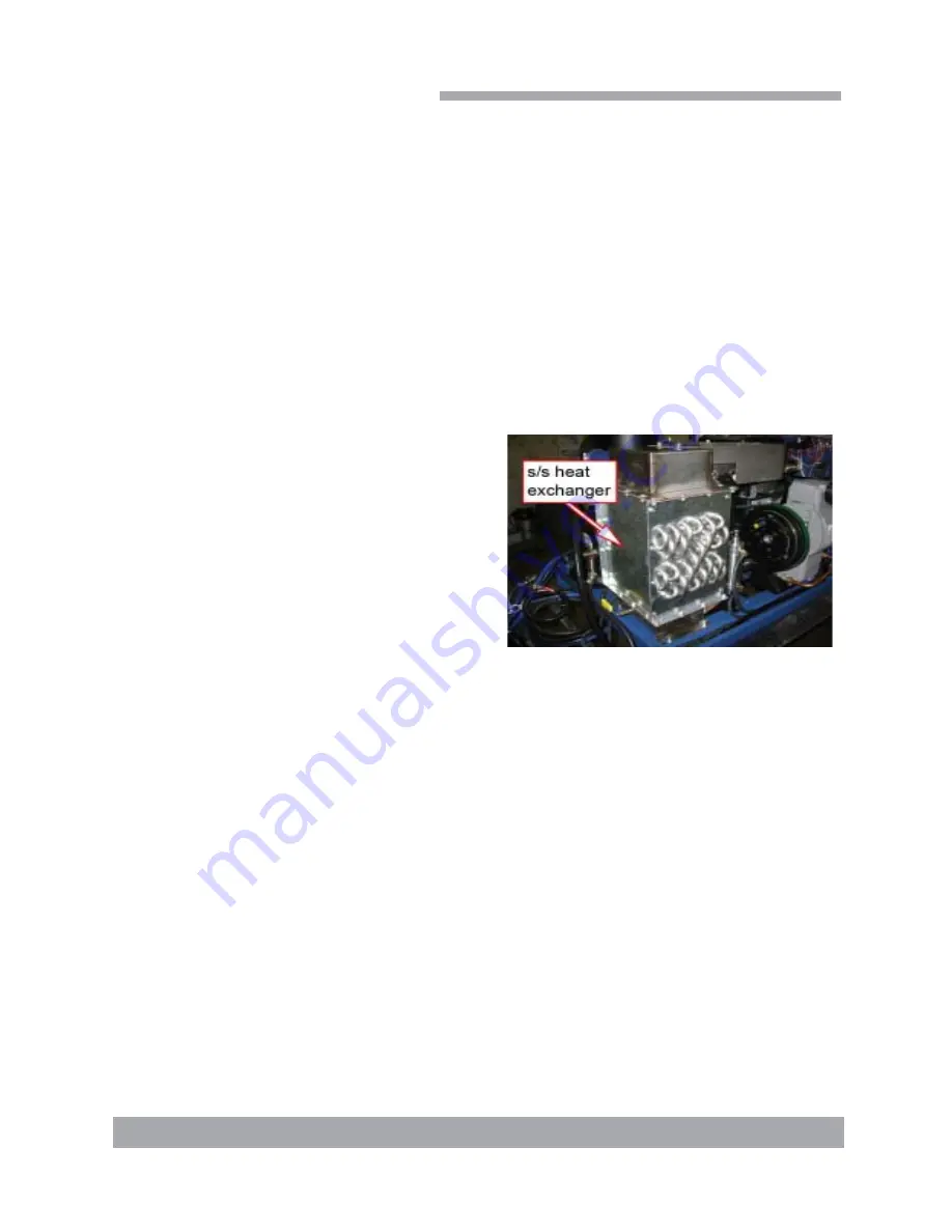
The heat exchange system (

Figure 5

) elevates the cleaning solution to the desired

temperature.  This system is comprised of two main components:  The components are
the engine/blower exhaust heat exchanger and the diverter valve system.  The engine/
blower exhaust heat exchanger is a cross-flow heat exchanger; solution flows through
the stainless steel tubes which flows the mixed exhaust along the outside.

The heating process begins when the mixed exhaust flows through the heat exchanger.
The cleaning solution is heated by the mixed exhaust as it flows through the coils of the
heat exchanger.  Once the cleaning solution has passed through the heat exchanger
the flow is directed to the outlet manifold then to the cleaning tool.

The 

compressor valve

’s purpose  is to manually relieve the system of compressed air.

This is done in situations such as removing the lids on the solution tanks.

Figure 9-1

Содержание CTS 330

Страница 1: ...ington 98275 No part of this manual may be reproduced or used in any form or by any means i e graphic electronic photocopying or electronic retrieval systems without the express written permission of...

Страница 2: ......

Страница 3: ...ON Section 1 Telephone Numbers 1 2 Precautions 1 3 Responsibilities 1 6 Vehicle Preparation 1 8 High Altitude Operation Preparation 1 12 Local Water Precautions 1 13 Hard Water Advisory 1 13 Hard Wate...

Страница 4: ...2 Shut Down 3 3 Safety Shutdown 3 3 General Operating Information 3 3 MACHINE MAINTENANCE Section 4 Engine 4 1 Air Filter 4 1 Engine Oil and Filter Change 4 2 Spark Plug Replacement 4 3 Fuel Filter 4...

Страница 5: ...LISTS Section 5 COMPRESSOR SYSTEM Section 6 VACUUM SYSTEM Section 7 Vacuum System Troubleshooting 7 3 Miscellaneous Troubleshooting 7 4 ELECTRICAL SYSTEM Section 8 WATER AND CHEMICAL SYSTEM Section 9...

Страница 6: ...hine maintenance Machine Assemblies and Parts Lists 5 1 Fig 5 1 Machine Assembly Front Right View 5 1 Fig 5 2 Machine Assembly Front Left View 5 2 Fig 5 3 Machine Assembly Rear View 5 3 Fig 5 4 Frame...

Страница 7: ...bly 5 33 Fig 5 21 15 Gallon Chemical Tank Assembly 5 35 Fig 5 22 Recovery Tank Assembly 5 37 Fig 5 23 Dura Flow APO Assembly 5 40 Fig 5 24 Vacuum Relief Assembly 5 42 Table 8 1 Ignition Switch Termina...

Страница 8: ...HydraMaster Corporation CTS 330 Owner s Manual CTS 330Hot Carbonating Truckmount System Fuel Pump Assembly B4627 Quick Reference...

Страница 9: ...nce Unlike a garden tractor lawn mower or cement mixer all having one or two functions to perform the truckmounted carpet cleaning plant has many functions to perform simulta neously The engine has to...

Страница 10: ...used to warn of possible equipment damage Telephone Numbers CTS Installer _________________ ____________ HydraMaster ChemDry Tech Support 877 282 2319 HydraMaster Customer Service 800 426 1301 Harris...

Страница 11: ...Parts Never touch any part of the machine that is in motion Severe bodily injury may result 4 Freeze Protection There is often little warning before a cold spell Failure to protect this equipment fro...

Страница 12: ...ws air conditioning units or kitchen fans 9 Toxic Fumes Do not occupy the vehicle when the cleaning equipment is operating Toxic fumes may accumulate inside a stationary vehicle 10 Engine Exhaust The...

Страница 13: ...maximum of 12 inches Hg will be attained At the end of each day an oil based lubricant should be sprayed into the blower lubrication port before shutting down the machine If this operation is not per...

Страница 14: ...ent Installer responsibilities are ACCEPTANCE OF SHIPMENT 1 If the unit shows any outward signs of damage do not sign the delivery receipt until you have closely inspected the unit and noted any damag...

Страница 15: ...operation manual with purchaser A thorough review of the unit warranty and warranty procedures Instruction and familiarization in 1 How to correctly start up and shut down the unit 2 How to correctly...

Страница 16: ...r recommends the installation of a spray on bed liner in the vehicle prior to installation of machine Be cautious when drilling any holes through the van floor Many vans have critical components mount...

Страница 17: ...ugh this location partly limits working access it does direct the noise away from the cleaning site Some cleaners in the colder areas prefer this location because it puts the weight over the rear whee...

Страница 18: ...plied A sudden or crash stop will cause the machine to rocket forward Protect yourself and the machine SECURE IT It is recommended by the manufacturer that the exhaust from the front of the machine be...

Страница 19: ...tion and by federal and state regulation The engine exhaust from this product contains chemicals known to the State of California to cause cancer birth defects or other reproductive harm If the batter...

Страница 20: ...air is provided to the fuel mixture This will make the engine run rich and in turn will result in the loss of power excessive heat in the exhaust and carbon buildup in the exhaust and heat ex changer...

Страница 21: ...prevent scale build up can result in system fail ure and loss of warranty on affected parts HARD WATER AREA MAP The hard water map on page 1 15 defines areas in the United States which compromise flui...

Страница 22: ...ms rivers and reser voirs IN ACCORDANCE WITH THE EPA STATE AND LOCAL LAWS DO NOT DISPOSE OF WASTE WATER INTO GUTTERS STORM DRAINS STREAMS RESERVOIRS ETC In most cases an acceptable method of waste wat...

Страница 23: ...Page 1 15 CTS 330 Owner s Manual CTS 330Hot Carbonating Truckmount System Figure 1 4 Hard Water Map...

Страница 24: ...hill 3003 Competitor Plus Solution System Dual high pressure tank compressed air fed Heating System Stainless steel cross flow exhaust heat exchanger Drive System Direct coupling rubber Instruments an...

Страница 25: ...e power console Full instrumentation Thomas air compressor Tuthill Competitor Plus Vacuum Blower Stainless steel water heating package Vacuum recovery tank 1 fifteen gallon stainless steel solution ta...

Страница 26: ...purged from the system Solution Valve Allows priming of the high temperature solution to be purged from the system Solution Outlet Hook up for the 3 16 solution hose Lube Port Allows the blower to be...

Страница 27: ...scriptions The engine produces the power required to operate the vacuum pump and air com pressor Figure 2 1 The vacuum pump is driven through the direct coupler by the engine Figure 2 2 The air compre...

Страница 28: ...ill void the warranty Carpet or Upholstery Cleaning 1 Fill solution tank with solution 2 Position the Compressor Valve to CLEANING MODE 3 Position the Solution Valve to CLEANING MODE 4 Change Cleaning...

Страница 29: ...in the CLEANING MODE this may cause damage to the air compressor and related components The Solution Valve must be positioned in the PRIME mode during flood extraction If the valve is left in the CLE...

Страница 30: ...filter bag End of Day Safety Shut Down This machine is equipped with two safety shutdowns This will alert you by shutting down the machine The two machine shutdowns are 1 Machine Overheat This will a...

Страница 31: ...ug gap Change fuel filter Visually check compressor belt Tighten belt Loosen belt Check exhaust system donut gaskets Engine Air Filter 1 Unlock the two clamps and remove cover Figure 4 1 2 Remove air...

Страница 32: ...of the engine Figure 4 3 3 Apply oil to the new oil filter gasket Install oil filter HRI part 049 014 4 Remove the oil fill cap located on top of the valve cover 5 Begin filling engine with 30W After...

Страница 33: ...s with a gap of 0 030 Champion Part RC12YC HRI Part 000 106 016 4 Re install the spark plug wires Fuel Filter The fuel filter is located underneath the van It is between the fuel filler neck and the f...

Страница 34: ...hat it reaches over half the sight glass Tools 11 16 wrench 5 8 wrench Grease gun 1 Remove the oil drain cap which is located on the oil drain hose on the side of the machine Figure 4 7 2 Remove oil f...

Страница 35: ...f Box 1 Remove the filter bag and clean Figure 4 8 Per form this operation after every cleaning job 2 Remove stainless steel filter Figure 4 9 3 Clean the stainless steel filter of debris daily This f...

Страница 36: ...ce Clean orifice Inspect manifold Rinse tanks Orifice Quick Connect Assembly The orifice assembly is located on the side of the solution tank bracket in line with the outlet hose The purpose of the or...

Страница 37: ...buildup on the exhaust side If required have the heat exchanger core cleaned or professionally descaled General Maintenance 1 Inspect hoses 2 Inspect wire connections 3 Check nuts belts and hose clam...

Страница 38: ...VE SYSTEM tighten screws 25 COMPRESSOR BELTS PULLEYS check for wear HRI Part 000 010 122 Gates Belt HD9465 25 HIGH PRESSURE LINES check for chafing 25 NUTS BOLTS check tightness 25 VACUUM RELIEF VALVE...

Страница 39: ...Page 5 1 CTS 330 Owner s Manual Hot Carbonating Truckmount System CTS 330 Machine Assemblies and Parts Lists Figure 5 1 Machine Assembly Front Right View D 6150 Rev C 1 4 5 13 12 11 9 10 6 7 8 18 3 19...

Страница 40: ...HydraMaster Corporation Page 5 2 CTS 330 Owner s Manual CTS 330Hot Carbonating Truckmount System Figure 5 2 Machine Assembly Front Left View D 6150 Rev C 2 17 16 17 14 15 14 18...

Страница 41: ...Page 5 3 CTS 330 Owner s Manual Hot Carbonating Truckmount System CTS 330 Figure 5 3 Machine Assembly Rear View D 6150 Rev C 8 6 7 2...

Страница 42: ...1 6 000 174 049 Washer 5 16 Flat 4 7 000 174 018 Washer 5 16 Lock 4 8 000 143 011 Screw Hhcs 5 16 18 x 1 2 4 9 000 174 001 Washer 10 Flat 1 10 000 174 014 Washer 10 Lock 1 11 000 143 126 Screw 10 24U...

Страница 43: ...Page 5 5 CTS 330 Owner s Manual Hot Carbonating Truckmount System CTS 330 Figure 5 4 Frame Assembly Front Left View D 6151 Rev B 7 9 5 1 2 8 4 17 16 14 15 3 6...

Страница 44: ...HydraMaster Corporation Page 5 6 CTS 330 Owner s Manual CTS 330Hot Carbonating Truckmount System Figure 5 5 Frame Assembly Front Right View D 6151 Rev b 10 27 29...

Страница 45: ...Carbonating Truckmount System CTS 330 Figure 5 6 Frame Assembly Rear View D 6151 Rev B DASH REMOVED FOR CLARITY 21 22 26 25 25 26 28 19 21 27 18 13 11 12 30 30 19 TO RECOVERY TANK TO CHEMICAL TANK TO...

Страница 46: ...000 174 001 Washer 10 Flat 1 12 000 174 014 Washer 10 Lock 1 13 000 143 126 Screw 10 24UNC x 0 50 Lg Hex Head 1 14 000 015 920 Bracket Compressor Guide 1 15 000 143 012 Screw 5 16 18UNC x 0 75 Lg Hex...

Страница 47: ...Page 5 9 CTS 330 Owner s Manual Hot Carbonating Truckmount System CTS 330 17 18 11 16 6 7 13 24 25 26 1 9 33 3 34 36 35 32 31 4 27 37 Figure 5 7 Dash Assembly Front View D 6152 Rev B...

Страница 48: ...30 Owner s Manual CTS 330Hot Carbonating Truckmount System 18 19 5 22 22 19 18 12 19 18 10 18 19 7 16 11 19 18 20 26 25 24 23 15 26 25 24 18 20 14 8 28 28 18 20 29 30 2 3 21 9 1 4 18 19 39 40 Figure 5...

Страница 49: ...se Holder Inline Weather Proof 1 13 000 052 272 Cup Gravity Feed Oil Blower Lubrication Port 1 14 000 012 002 Block 6 Post Terminal 1 15 000 052 096 Insert F23 1 8 FPT x 3 16 Barb 1 16 000 074 025 Gau...

Страница 50: ...List Item Part Number Description Qty 32 000 140 001 Rivet 1 8 x 1 4 Aluminum 2 33 000 081 243 Label Dash 1 34 000 081 243 Label Blower Lube Port 1 35 000 081 243 Label Engine Produces Toxic Gas 1 36...

Страница 51: ...Page 5 13 CTS 330 Owner s Manual Hot Carbonating Truckmount System CTS 330 Figure 5 9 HI PSI Manifold Assembly C 6158 Rev A 12 6 7 10 6 11 14 2 6 8 9 1 8 3 4 5 13...

Страница 52: ...4 014 Washer 10 Lock 2 5 000 143 166 Screw 10 24UNC x 0 38 Lg Hex Head 2 6 000 052 691 Elbow 1 4 Street s s 3 7 000 052 506 Nipple 1 4 NPT x 9 16 18UNF x 37 JIC 1 8 000 052 095 Nipple 1 4 NPT Hex 2 9...

Страница 53: ...Page 5 15 CTS 330 Owner s Manual Hot Carbonating Truckmount System CTS 330 Figure 5 10 Purge Valve Assembly C 6161 Rev A 13 11 8 3 3 1 4 5 6 7 2 9 10 3 13 12...

Страница 54: ...3 000 052 100 Insert 44 1 4 NPT x 1 4 Barb 3 4 000 174 001 Washer 10 Flat 2 5 000 174 014 Washer 10 Lock 2 6 000 143 166 Screw 10 24UNC x 0 38 Lg Hex Head 2 7 000 052 090 Tee 1 4 NPT Branch M F F 2 8...

Страница 55: ...Page 5 17 CTS 330 Owner s Manual Hot Carbonating Truckmount System CTS 330 Figure 5 11 Vacuum Solenoid Valves Assembly C 6162 Rev 9 6 7 10 8 7 5 4 2 1 5 4 2 11 8 6 8 8 6 12 3 3...

Страница 56: ...Primary Vac Solenoid 2 3 000 106 014 Plug Gearbox Vent 2 4 000 052 106 Insert 1 8 NPT x 5 32 Barb x 90 4 5 000 143 047 Screw 6 32UNC x 7 8 Lg Pan Head Phillips 4 6 000 052 155 Tee 3 16 Plastic Vacuum...

Страница 57: ...Page 5 19 CTS 330 Owner s Manual Hot Carbonating Truckmount System CTS 330 Figure 5 12 Engine Assembly Left View D 6153 Rev C 6 18 22 16...

Страница 58: ...tion Page 5 20 CTS 330 Owner s Manual CTS 330Hot Carbonating Truckmount System Figure 5 13 Engine Assembly Right View D 6153 Rev C 13 12 14 1 3 11 5 7 8 9 10 19 17 2 12 20 21 12 19 23 17 14 12 12 20 1...

Страница 59: ...18 Washer 5 16 Lock 4 9 000 143 015 Screw 5 16 18UNC x 1 50 Lg Hex Head 4 10 000 052 106 Insert 1 8 NPT x 5 32 Barb x 90 1 11 000 077 010 Key 1 4 x 1 1 2 Lg Class 2 Fit 1 12 000 174 003 Washer 1 4 Fla...

Страница 60: ...5 22 CTS 330 Owner s Manual CTS 330Hot Carbonating Truckmount System Figure 5 14 Exhaust Assembly D 6155 Rev B 21 13 18 14 15 9 8 7 6 5 8 1 8 8 9 11 16 17 17 16 23 24 22 25 4 3 2 19 26 12 31 27 27 27...

Страница 61: ...be Diverter Outlet 1 13 000 125 211 Tube Heat Exchanger Outlet Welded 1 14 000 001 116 Adapter 1 50 F Slip To Flare 1 15 000 033 068 Clamp 1 1 2 Muffler 1 16 000 125 128 Tube 1 3 8 OD x 1 8 Wall x 7 8...

Страница 62: ...HydraMaster Corporation Page 5 24 CTS 330 Owner s Manual CTS 330Hot Carbonating Truckmount System Figure 5 15 Diverter Valve Actuator Assembly C 6154 Rev A 6 1 2 3 8 9 10 5 4 4 7...

Страница 63: ...015 922 Bracket Air Cylinder Extension 1 3 000 094 092 Nut 7 16 20UNF Hex Jam 1 4 000 052 106 Insert 1 8 NPT x 5 32 Barb x 90 2 5 000 015 750 Bracket Air Cylinder Mount Inner 1 6 000 015 748 Bracket...

Страница 64: ...HydraMaster Corporation Page 5 26 CTS 330 Owner s Manual CTS 330Hot Carbonating Truckmount System Figure 5 16 Blower Assembly Front View D 6156 Rev A 2 1 7 4 5 11 3 10 9 6 12 8 13...

Страница 65: ...Page 5 27 CTS 330 Owner s Manual Hot Carbonating Truckmount System CTS 330 Figure 5 17 Blower Assembly Rear View D 6156 Rev A 14 15 13...

Страница 66: ...049 Washer 5 16 Flat 4 5 000 174 018 Washer 5 16 Lock 4 6 000 143 014 Screw 5 16 18UNC x 1 25 Lg Hex Head 4 7 000 174 068 Washer Blower Feet 4 8 000 052 106 Insert 1 8 NPT x 5 32 Barb x 90 2 9 000 02...

Страница 67: ...CTS 330 Owner s Manual Hot Carbonating Truckmount System CTS 330 Figure 5 18 Compressor Assembly D 6157 Rev D 13 19 17 20 4X 15 4X 14 4X 21 4X 20 4X 6 5 4 16 20 8 1 20 4X 8 4X 9 11 4X 12 4X 3 22 15 1...

Страница 68: ...ock 5 9 000 105 323 Plate Compressor Clutch Mount 1 10 000 111 204 Pump Compressor Thomas SGH 617b 1 11 000 143 001 Screw 1 4 20UNC X 0 75 Lg Hex Head 4 12 000 143 141 Screw 1 4 20UNC X 1 2 Lg Whiz Lo...

Страница 69: ...Page 5 31 CTS 330 Owner s Manual Hot Carbonating Truckmount System CTS 330 Figure 5 19 Blower Heat Exchanger Assembly D 6159 Rev A 4 5 5 15 2 20 13 3 10 11 20 6 7 8 5 16 5 12 17 18 19 1 15 9 14 21...

Страница 70: ...16 Lock 4 8 000 143 012 Screw 5 16 18UNC x 0 75 Lg Hex Head 4 9 000 052 749 Insert 64 3 8 NPT x 1 4 Barb 1 10 000 052 744 Compression 1 8 NPT x 1 8 Tube Modified 1 11 000 149 054 Sensor K Type Thermoc...

Страница 71: ...age 5 33 CTS 330 Owner s Manual Hot Carbonating Truckmount System CTS 330 Figure 5 20 15 Gallon Chemical Jug Assembly D 6163 Rev B 7 8 7 5 1 4 10 TO HEAT EXCHANGER TO COMPRESSOR 9 3 2 11 12 11 6 14 13...

Страница 72: ...ocket Out s s 90 Barb 1 4 000 159 127 Tank 15 Gallon Chemical 1 5 000 108 141 Tie Down Strap 1 6 000 068 015 Hose 1 4 I D Bulk 1 7 000 033 003 Clamp Size 4 Mini 3 8 000 068 131 Hose 1 4 Silcone 1 9 00...

Страница 73: ...Page 5 35 CTS 330 Owner s Manual Hot Carbonating Truckmount System CTS 330 Figure 5 21 15 Gallon Chemical Tank Assembly C 6109 Rev 1 2 3 4 5 4...

Страница 74: ...kmount System 15 Gallon Chemical Tank Assembly Parts List Item Part Number Description Qty 1 000 159 126 Tank 15 Gallon Chemical 1 2 000 106 055 Plug 1 4 s s Chemical Container 1 3 000 097 006 O Ring...

Страница 75: ...330 Owner s Manual Hot Carbonating Truckmount System CTS 330 Figure 5 22 Recovery Tank Assembly D 5530 Rev D 10 12 9 3 10 9 4 5 24 25 6 27 28 24 25 6 7 11 23 22 13 9 14 15 19 17 21 16 20 9 12 10 18 2...

Страница 76: ...2 NPT x 1 1 2 Barb Grey 1 12 000 086 008 Latch Bungie Strike 2 13 000 052 090 Tee 1 4 NPT Branch M F F 1 14 000 052 082 Elbow 1 4 NPT Street x 45 1 15 000 131 021 Trimlok 5 8 x 1 8 1 16 000 052 219 Ad...

Страница 77: ...Page 5 39 CTS 330 Owner s Manual Hot Carbonating Truckmount System CTS 330 Figure 5 23 Dura Flow APO Assembly D 5654 Rev B 16 15 16 17 18 19 20 21 17 1 9 10 5 8 3 8 2 7 6 13 4 14 12 7 4 6 6 5 22...

Страница 78: ...tting 1 NPT Cam Lock Banjo 100F 1 10 000 052 724 Fitting 1 NPT Cam Lock Banjo 100B 1 11 000 157 022 Switch Relay 1 12 000 012 011 Block 6 Post 1 13 000 094 027 Nut 10 24UNC Hex 1 14 000 143 532 Screw...

Страница 79: ...Page 5 41 CTS 330 Owner s Manual Hot Carbonating Truckmount System CTS 330 Figure 5 24 Vacuum Relief Valve Assembly C 4237 Rev B 7 7 5 3 1 4 8 2 6 USE BLUE LOCKTITE 242...

Страница 80: ...y 1 000 015 182 Bracket Vacuum Relief Valve 1 2 000 027 032 Cap Vacuum Relief Valve 1 3 000 125 111 Pipe Vacuum Relief Spring Guide 1 4 000 105 067 Plate Vacuum Relief Valve Mounting 1 5 000 155 026 S...

Страница 81: ...e compressor With the cleaning mode switch in Extraction Mode the clutch will turn off regardless of the pressure in the solution tank The compressor should be well ventilated Objects place or install...

Страница 82: ...s and the vacuum inlet on top of the machine is open To protect the vacuum blower from overloading and damaging itself there is a vacuum relief system installed on the vacuum tank When the vacuum tank...

Страница 83: ...oam only by liquid VACUUM TANK FILTER BAGS HydraMaster filter bags are designed to trap lint sand and dirt that would normally collect at the bottom of your vacuum tank The use of these bags if emptie...

Страница 84: ...recovery tank lid gasket Make sure recovery tank drain valve is fully closed 2 2 Vacuum blower is turning too slowly Check engine RPM Adjust as necessary to 3000RPM 2 3 The vacuum gauge is defective T...

Страница 85: ...been filled with foam or overfilled with water Remove recovery tank lid and inspect If full drain tank then inspect high level shutoff switch for proper operation Clean or replace switch as necessary...

Страница 86: ...a new battery is installed check that it is properly charged before installation or damage to the charging system may occur The orange wire going from the engine starter solenoid to terminal 5 on the...

Страница 87: ...GRN WHT 26 BRN WHT ORG ORG 30 AMP FUSE FU 1 21 BLK 21 BLK 28 WHT GRN 27 GRN 27 GRN 4 ORG WHT 3 ORG TO REC TANK PLUG P 5 D 3 ORG 6 BLK WHT 2 WHT GRY TO FUEL PUMP 2 WHT GRY TO ENGINE KILL LUG 12 BLK TO...

Страница 88: ...3 ORG 4 ORG WHT P 5 WHT BLK RECOVERY TANK ASSEMBLY FS 1 VACUUM TANK HIGH WATER J 5 4 ORG WHT TO TB 1 4 3 ORG TO GND 1 P 2 J 2 13 WHT TO IGN SWITCH 2 P 1 J 1 13 WHT 5 RED 5 RED TO MAIN FUSE B 1 12 GA...

Страница 89: ...ENSOR APO SWITCH OFF SW 5 ON STATOR GND GND TC 1 CONTROLLER TEMPERATURE TR4 TR5 TR3 GND GND TB2 1 TB2 2 KILL LUG ENGINE TR6 TR7 TR8 TR2 TR1 TR9 GND FU 1 30A FUSE GND 5 3 1 2 6 4 GND MODE MODE PRESSURE...

Страница 90: ...gger is in use and the solution is at the desired temperature the chemical solution will flow through the solution outlet The solution valve and the pop off valve send the solution to the recovery tan...

Страница 91: ...in situations such as Flood Damage Mode or in a case of the machine running for an extended period of time with no solution hoses hooked up The pressure build up in the heat exchangers and hoses can...

Страница 92: ...Page 9 3 CTS Owner s Manual CTS 330Hot Carbonating Truckmount System Figure 9 2 Solution Flow Diagram D 6168 Rev...

Страница 93: ...Page 9 5 CTS Owner s Manual CTS 330Hot Carbonating Truckmount System...

Страница 94: ...ll not turn refer to Vacuum Troubleshooting in Section 6 3 1 5 The ignition switch is defective Test to see if there is 12 volts to the switch If there is but there is not 12 volts going from the swit...

Страница 95: ...2 4 The high temperature switch has shut the engine down Observe the tem perature gauge If it is above the normal operating range allow the machine to cool down If it will still not start disconnect t...

Страница 96: ...0 hg and 12 hg Too high or too low will cause severe damage to machine components 4 2 There is excessive load on the engine due to the blower to recovery tank hose becoming delaminated Remove and insp...

Страница 97: ...necessary 6 3 Excessive fuel to carburetor Insure that fuel pump is proper PSI rating A fuel pump with a psi rating in excess of that of the pump supplied with the machine could overpower the inlet va...

Страница 98: ...ard systems such as waste tank filter screen vacuum safety relief valve and waste tank automatic shut off system Allowing foam to pass through blower Vacuum Tank Failure to properly maintain filtering...

Страница 99: ...d shall be proved to HydraMaster s satisfaction to have been de fective when shipped provided the purchaser promptly notifies HydraMaster in writing of such alleged defect HydraMaster will pay all fre...

Страница 100: ...filter using compressed air DO NOT CLEAN FILTERWITHPETROLEUMBASEDPRODUCTS Replace felt insert after several cleanings OSHA SPECIFICATION REQUIRE ALL BREATHING AIR SYSTEMS TO MEET THE STANDARDS AS SPEC...

Страница 101: ...050 P SGH 401B C87050 P 1 2 2 SGH 5VB C87226 P SGH 505B C87226 P SGH 510B C87050 P 3 4 2 SGH 6VB C87053 P SGH 605B C87226 P SGH 610B C87050 P 1 2 SGH 705B C87053 P SGH 710B C87226 P 3 H P ENG 2 SGH E1...

Страница 102: ...d discharge Tuthill Vacuum Blower Systems Competitor model rotary lobe blowers are positive displacement type units whose pumping capacity is determined by size operating speed and differential pressu...

Страница 103: ...ally be adjusted to obtain desired capacity by changing the diameter of one or both sheaves or by using a vari speed motor pulley In a direct coupled arrangement a variable speed motor or transmission...

Страница 104: ...apacities are based on filling from dry condition Less oil may be needed depending on emptiness of oil reservoir s after draining Always fill the gear housing until oil drips out of the oil level hole...

Страница 105: ...otor end clearances greater than shown within the Assembly Clearances table will not have the operating limits specified here Contact your Tuthill Vacuum Blower Systems sales representative for specif...

Страница 106: ...of the blower supports an equal share of the blower weight This is necessary to prevent eventual twisting of the blower Make sure feet rest evenly on the mounting surface before fastening down Twistin...

Страница 107: ...nst rusting in normal atmospheric conditions prior to installation The maximum period of internal protection is considered to be up to 6 months under average conditions provided closing plugs and seal...

Страница 108: ...en foot and base soft foot shim as necessary to fill gap within 002 05 mm Below are shown the two most common types of soft foot conditions If either type is present and measures more than 003 076 mm...

Страница 109: ...stallation point Both independent oil reservoirs must be filled to the proper level before operation Oil reservoirs are under vacuum Shaft bearings at the gear end of the blower are splash lubricated...

Страница 110: ...e end plates 2 SLOWLY pour oil through fill until oil appears in the oil sight glass Bring oil level to center of sight glass 3 Verify oil level is at proper level in BOTH gear end and drive end sight...

Страница 111: ...dicator of the breakdown of a lubricant is the increase in the TAN Total Acid Number and a change in the base viscosity of ten percent Several things are happening as the lubricant goes through the un...

Страница 112: ...distortion of the blower Use proper supports and pipe hangers to assure that there is no loading Inlet and outlet connections on all blowers are large enough to handle maximum volume with minimum fric...

Страница 113: ...with the two shafts not having more than 005 13 mm T I R Total Indicator Reading Face must be aligned within 002 05 mm Proper gap between coupling halves must be established according to coupling man...

Страница 114: ...A visual inspection of the V belt drive should yield the appearance shown in Figure 6 Factors outside the control of the belt tensioning system used on an individual blower package assembly may contri...

Страница 115: ...oves worn Replace sheaves Sheave diameter too small Redesign drive Mismatched belts Replace with matched belts Drive overloaded Redesign drive Belt slips Increase tension Sheaves misaligned Align shea...

Страница 116: ...otor is properly lubricated and that it is connected through suitable electrical overload devices 6 With electrical power off and locked out to prevent accidental starting rotate blower shaft several...

Страница 117: ...s freely and smoothly Start the unit and operate it for 30 minutes at no load During this time feel the cylinder for hot spots If minor hot spots occur refer to the Troubleshooting chart Apply the loa...

Страница 118: ...the unit along with the air gas being compressed A blower cooled in this manner can operate safely at higher vacuums or higher inlet temperatures than a normally uncooled unit The amount of water req...

Страница 119: ...iron internal surfaces or in cold weather the formation of ice Either of these conditions can close the operating clearances causing the blower to fail upon future start up The following shutdown pro...

Страница 120: ...require internal protection against rusting or corrosion The need for such protection must be a matter of judgment based on existing conditions as well as length of down time Under atmospheric conditi...

Страница 121: ...s not covered in this book should be referred to the nearest Tuthill Vacuum Blower Systems service representative When ordering parts give all blower nameplate information as well as the item number a...

Страница 122: ...period of time you should take make sure that it is protected from corrosion by following these steps 1 Spray the interior lobes housing and end plates with rust preventative This should be repeated...

Страница 123: ...e gear cover It may be necessary to tap the sides with a mallet or wooden block to break the seal joint NOTE Gears are not exposed for visual inspection Inspect the gears for the following Broken Teet...

Страница 124: ...slightly smaller diameter than the shaft clearance holes in the end plates tap the bearings out of the end plates Bearing retainers 22 must be removed before knocking out the bearings Refer to Figure...

Страница 125: ...and 20 8 2 1 MECHANICAL SEAL INSTALLATION 1 Clean and deburr seal bore in endplate Clean the face of the carbon and mating ring with alcohol etc Apply a thin layer of silicon to the bottom face of the...

Страница 126: ...drive end cover 10 that mates to the drive end plate 3 Install drive end cover and drive shaft seal 23 12 Install any removed plugs 18 sight glasses 21 and replace breather 27 if required 8 2 2 LUBRI...

Страница 127: ...ed or 003 08 mm AA should then read 006 15 mm and BB should read 006 15 mm The final reading should be within 002 05 mm of each other 19 To determine the amount of shim to add or remove subtract the s...

Страница 128: ...Reduce to manufacturer s recommended pressure Examine relief valve and reset if necessary Worn gears Replace timing gears See the Disassembly section Excessive blower temperature Too much or too littl...

Страница 129: ...0 15 009 013 29 33 014 018 36 46 003 006 08 15 005 008 13 20 5006 005 010 13 25 004 006 10 15 010 014 25 36 014 018 36 46 003 006 08 15 005 008 13 20 5009 005 010 13 25 004 006 10 15 010 014 25 36 014...

Страница 130: ...S TUTHILL CITGO Tuthill PneuLube NLGI 2 premium grade petroleum base lithium grease For food grade requirements Use Citgo Clarion Food Grade HTEP grease NLGI No 2 grade It meets all requirements of FD...

Страница 131: ...44 069 0 220 5 588 2 832 71 933 2 434 61 824 0 1745 4 432 2 6745 67 932 MODEL L M N P Q R S T U V 3000 2 183 55 448 1 253 31 826 2 000 50 8 0 500 12 7 1 749 44 425 0 500 12 7 4 275 108 585 3 775 95 8...

Страница 132: ...AL 4 25 SCREW HEX HEAD 12 26 WASHER 2 27 BREATHER 1 28 SPACER 2 29 CAP SCREW 2 30 SHIM 6 30 SHIM 6 30 SHIM 4 31 KEY GEAR 2 42 NAMEPLATE 1 45 LIFTING LUG 2 47 VENT HOLE INSERT 8 NOTES QUANTITIES SHOWN...

Страница 133: ...AGNETIC PLUG 2 21 OIL SIGHT GLASS 2 22 BEARING RETAINER 2 23 LIP SEAL 1 24 LIP SEAL 4 25 SCREW HEX HEAD 12 26 WASHER 3 27 BREATHER 2 28 SPACER 2 29 CAP SCREW 3 30 SHIM 6 30 SHIM 6 30 SHIM 4 31 KEY GEA...

Страница 134: ...CREW HEX HEAD 4 18 PIPE PLUG 2 18 MAGNETIC PLUG 2 21 OIL SIGHT GLASS 2 22 BEARING RETAINER 2 23 LIP SEAL 1 25 SCREW HEX HEAD 4 26 WASHER 3 27 BREATHER 2 28 SPACER 2 29 CAP SCREW 3 30 SHIM 6 30 SHIM 2...

Страница 135: ...38 CUTAWAY DRAWING FOR 21 PLUS SERIES 25 17 2 6 23 20 19 11 7 10 15 3 30 18 17 28 31 29 24 15 1 9 8 5 27 15 4 13 26 16 22...

Страница 136: ...39 CUTAWAY DRAWING FOR 22 SL AND 23 GT SERIES 23 45 10 11 48 29 26 BOTH ENDS 21 28 31 30 50 44 16 18 46 47 17 29 17 2 27 15 12 3 15 24 9 1 6 7 8 26 5 4 15 27 16 25 22 16 13...

Страница 137: ...40 NOTES...

Страница 138: ...d standards that apply to this Declaration of Incorporation EN 1012 1 1996 Compressors and vacuum pumps Safety requirements Part 1 Compressors The scope of the Declaration of Incorporation is for bare...

Страница 139: ...Seller Unless done with prior written consent of Seller any repairs alterations or disassembly of Seller s equipment shall void warranty Installation and transportation costs are not included and def...

Страница 140: ...Number Date of Purchase Date of Startup IMPORTANT All blowers manufactured by Tuthill Vacuum Blower Systems are date coded at time of shipment In order to assure you of the full benefits of the produ...

Страница 141: ...IF MAILED IN THE UNITED STATES ATTN CUSTOMER SERVICE TUTHILL VACUUM BLOWER SYSTEMS PO BOX 2877 SPRINGFIELD MO 65890 2150 POSTAGE WILL BE PAID BY ADDRESSEE BUSINESS REPLY MAIL FIRST CLASS MAIL PERMIT N...

Страница 142: ......

Страница 143: ......

Страница 144: ......

Страница 145: ......

Страница 146: ......

Страница 147: ......

Страница 148: ......

Страница 149: ......

Страница 150: ......

Страница 151: ......

Отзывы: