29
4. Install bearing retainers [Items 22 & 25] to both bearings.
5. Check clearances between the end of the rotors and the face of the end plate. Refer to assembly
clearances chart on page 32 for proper clearances for your model blower, and refer to the
Adjusting
Rotor Interlobe Clearance
section on page 29 for procedures for checking and adjusting clearances.
6. If clearances check OK, put a spacer [28] and a shim [30] on each shaft. Timing shims that were
removed should be put back on the shaft from which they were removed.
7. Lubricate shafts and bores on gears. Begin by pressing on the DRIVE gear. This will be pressed on the
drive rotor, which is to the left.
8. Start the driver gear on the shaft and align the reference timing marks and press gear on. Lock gears in
place with socket head screw [29] and washer [26]. Turn assembly over and rest the unit on the socket
head screws and washers on the gear end.
9. Set dowel pins [9] in housing and position housing over the rotors and fasten with cap screws [15].
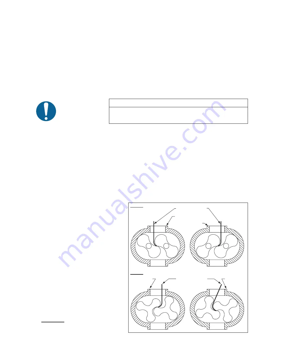
Check housing to rotor clearance. (Refer to Figure 21) A depth mic can be used.
10. Set on drive end plate [3] and fasten with cap screws [15].
NOTE
There are four cap screws [17] which are used to attach the feet.
Lubricate shafts and bearings. Install the ball bearing [12] on the driven rotor and the roller bearing [11]
on the input shaft.
11. Apply a bead of a good quality RTV silicone sealant to the inner surface of the drive end cover [10] that
mates to the drive end plate [3]. Install drive end cover and drive shaft seal [23].
12. Install any removed plugs [18], sight glasses [21] and replace breather [27] if required.
8.2.2 LUBRICATION, FINAL ASSEMBLY AND MOUNTING
13. Apply a bead of a good quality RTV silicone sealant to the inner surface of the gear end cover [5] that
mates to the gear end plate [4]. Install the gear end cover with cap screws [16] and tighten evenly.
14. Fill both end covers with oil. Refer to the
Lubrication
section of this manual (page 12) for fi lling procedure,
and page 34 for recommended
lubricants.
15. To insure blower has not been distorted
during mounting in the installation, turn
the lobes by hand to make sure they are
not making contact prior to connecting
to the driver.
8.2.3 ADJUSTING ROTOR
INTERLOBE CLEARANCE
16.
Using feeler gauges take interlobe
readings and record on each side of
housing as indicated in Figure 21. By
removing or adding shim behind the
helical gear, it rotates as it is moved in
or out and the driven rotor turns with it,
thus changing the clearance between
rotor lobes.
17. Changing the shim thickness .006” (.15
mm) will change the rotor lobe clearance
.003” (.08 mm) or one-half the amount.
18.
EXAMPLE:
Referring to Figure 21,
check the clearance at AA (right hand
reading) and BB (left hand reading). If
Figure 21 - Checking Rotor Interlobe Clearance
A
B
B
B
A
B
A
A
A
A
B
A
B
B
A
B
LONG FEELER GAUGE
LONG FEELER GAUGE
RECORD A-A
READING HERE
RECORD A-A
READING HERE
RECORD B-B
READING HERE
3 LOBE
2 LOBE
RECORD B-B
READING HERE
B
B
B
B
B
B
B
B
B
B
B
B
A
A
A
A
A
A
A
A
A
A
A
A
DRIVE
DRIVEN
DRIVE
DRIVEN
Содержание CTS 330
Страница 2: ......
Страница 23: ...Page 1 15 CTS 330 Owner s Manual CTS 330Hot Carbonating Truckmount System Figure 1 4 Hard Water Map...
Страница 93: ...Page 9 5 CTS Owner s Manual CTS 330Hot Carbonating Truckmount System...
Страница 137: ...40 NOTES...
Страница 142: ......
Страница 143: ......
Страница 144: ......
Страница 145: ......
Страница 146: ......
Страница 147: ......
Страница 148: ......
Страница 149: ......
Страница 150: ......
Страница 151: ......


