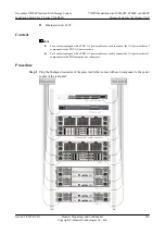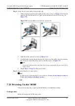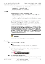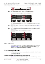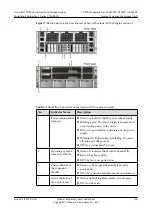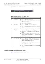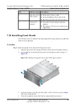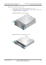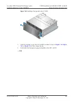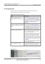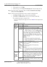
Figure 7-39
Indicators on the Ethernet switch
Table 7-5
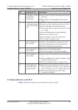
Checklist of indicators on the Ethernet switch
No.
Indicator Name
Description
1
Power indicator
l
Green on: The switch is powered on.
l
Orange on: The power supply unit is faulty, and the external
RPS system is started.
l
Off: The switch is powered off.
2
RPS indicator
l
Green on: The RPS is connected to the switch.
l
Off: The RPS is not connected to the switch or the RPS is
faulty.
3
System status
indicator
l
Green on: The system is not operating properly or is starting.
l
Green blinking: The system is operating properly.
l
Orange on: The system is performing self-check during
startup.
l
Red on: After registering, the system does not operate
properly, or a power alarm, fan alarm, or temperature alarm
is generated.
l
Off: The system is not operating.
4
Mode indicator
l
Green on: The service interface indicator indicates the
interface speed. After 45 seconds, the service interface
indicator automatically restores to off.
l
Red on: The service interface indicator indicates the stack
ID. After 45 seconds, the service interface indicator
automatically restores to off.
l
Off: The service interface indicator is in the default mode
(STAT).
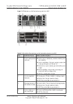
Checking Indicators on a Fibre Channel Switch
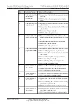
shows indicators on a Fibre Channel switch.
OceanStor N8500 Clustered NAS Storage System
Installation Guide (for T Series V100R005)
7 N8500 Installation (with S5600T, S5800T or S6800T
Storage System as the Storage Unit)
Issue 02 (2015-09-22)
Huawei Proprietary and Confidential
Copyright © Huawei Technologies Co., Ltd.
226

