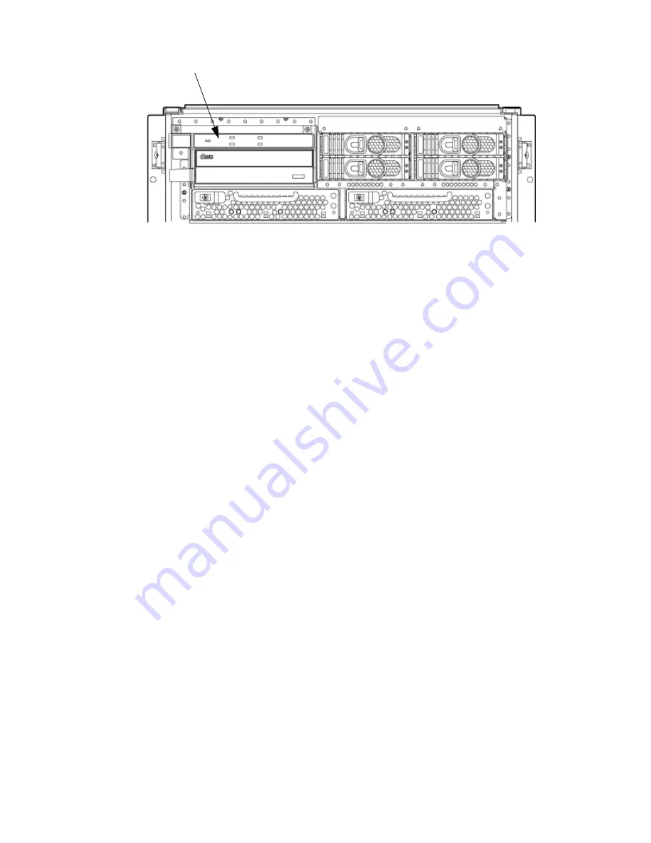
Figure 6-7 Front Panel Assembly Location
Front Panel Board
Removing the PCA Front Panel Board
1.
Remove the front bezel and the top and left side covers.
2.
Follow proper procedures to power off the server.
3.
Disconnect the SCSI cables from MSBP and move them out of the way.
This helps provide access to the common tray cage cover.
4.
Disconnect the DVD power cable from the mass storage backplane. (
5.
Disconnect the front panel cable from the system backplane. (
Figure 6-8
).
6.
Unscrew the captive fastener on the common tray cage cover.
7.
Apply firm pressure to slide the common tray cage cover to the rear, then lift. Place the cable
as far back as possible to gain clear access to the front panel.
8.
Remove the front panel bezel by removing the two screws. After the screws are removed,
press the tab in the center of the bezel to release the bezel.
9.
Remove the two screws revealed upon removing the bezel.
10. Place your left hand under the sheet metal wall that acts as a handle, and simultaneously,
gently lift the handle upward and pull on the cable. This action disengages the tabs on the
PCA front panel from the slots on the common tray cage
11. Gently pull the cable and handle toward the rear of the chassis until the steel power button
that was initially protruding though the chassis clears the hole.
12. Rotate the top edge of the board toward you about 30 degrees by lifting on the handle with
your left hand.
13. Angle the board such that the right side with the cable moves away from you and the opposite
side with the power connector moves towards you.
Ensure that the power switch does not get stuck in one of the many holes in the front of the
chassis. This rotation is best accomplished by gently pulling the cable with your right hand
toward the rear of the cabinet.
14. Remove the cable end of the board first by gently pulling the cable with your right hand
and adjusting the angle of the board with your left hand.
After the first tab on the board is outside the cavity, removal should proceed easily.
148
Removing and Replacing Components
Содержание Integrity rx7640
Страница 8: ...8 ...
Страница 12: ...12 ...
Страница 13: ...List of Examples 4 1 Single User HP UX Boot 101 7 1 Single User HP UX Boot 181 13 ...
Страница 14: ...14 ...
Страница 42: ...42 ...
Страница 88: ...88 ...
Страница 130: ...Figure 5 8 Core I O Button Locations OLR MP Reset 130 Server Troubleshooting ...
Страница 140: ...140 ...
Страница 176: ...176 ...
Страница 184: ...184 ...
Страница 191: ...Figure C 3 Planning Grid Computer Room Layout Plan 191 ...
Страница 192: ...Figure C 4 Planning Grid 192 Templates ...


