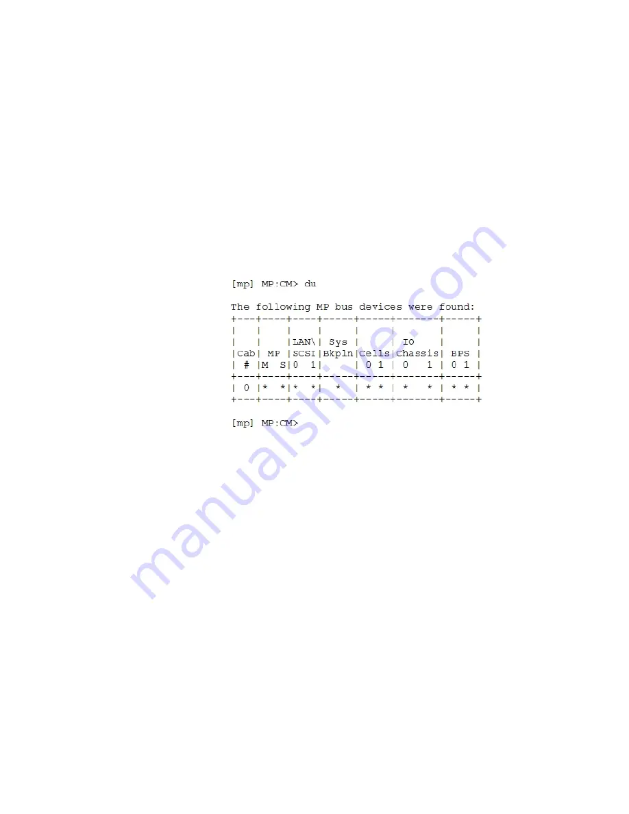
After logging in to the MP, verify that the MP detects the presence of all the cells installed in the
cabinet. It is important for the MP to detect the cell boards. If it does not, the partitions will not
boot.
To determine if the MP detects the cell boards:
1.
At the MP prompt, enter
cm
.
This displays the Command Menu. The Command Menu enables viewing or modifying the
configuration and viewing the utilities controlled by the MP.
To view a list of the commands available, enter
he
. Press Enter to see more than one screen
of commands. Use the Page Up and Page Down keys to view the previous or next screen of
commands. To exit the Help Menu, enter
q
.
2.
From the command prompt (MP:CM>), enter
du
.
The
du
command displays the MP bus topology. A screen similar to the following is
displayed:
Figure 3-35 The du Command Screen
There will be an asterisk (*) in the column marked MP.
3.
Verify that there is an asterisk (*) for each of the cells installed in the cabinet, by comparing
what is in the Cells column with the cells physically located inside the cabinet.
Figure 3-35
shows that cells are installed in slots 0 and 1. In the cabinet, cells should be
physically located in slots 0 and 1.
System Console Selection
Each operating system requires that the correct console type be selected from the firmware
selection menu. The following section describes how to determine the correct console device.
If an operating system is being installed or the system configuration is being changed the system
console setting must be checked to ensure it matches the hardware and OS. Not checking the
console selection can result in the system using an unexpected device as a console, which can
appear as a system hang when booting.
1.
Determine the console you want to use.
Depending on your operating system and your hardware you can select one of two possible
devices as your system console. The possibilities are:
•
Management Processor (MP) Serial Port
•
VGA device
Cabling and Power Up
81
Содержание Integrity rx7640
Страница 8: ...8 ...
Страница 12: ...12 ...
Страница 13: ...List of Examples 4 1 Single User HP UX Boot 101 7 1 Single User HP UX Boot 181 13 ...
Страница 14: ...14 ...
Страница 42: ...42 ...
Страница 88: ...88 ...
Страница 130: ...Figure 5 8 Core I O Button Locations OLR MP Reset 130 Server Troubleshooting ...
Страница 140: ...140 ...
Страница 176: ...176 ...
Страница 184: ...184 ...
Страница 191: ...Figure C 3 Planning Grid Computer Room Layout Plan 191 ...
Страница 192: ...Figure C 4 Planning Grid 192 Templates ...


