Scenario 3:1 – Multi-Enclosure stacking, with Multiple Simple vNets, Redundant Uplinks and LACP (2 Enclosures) 180
Figure 3-11
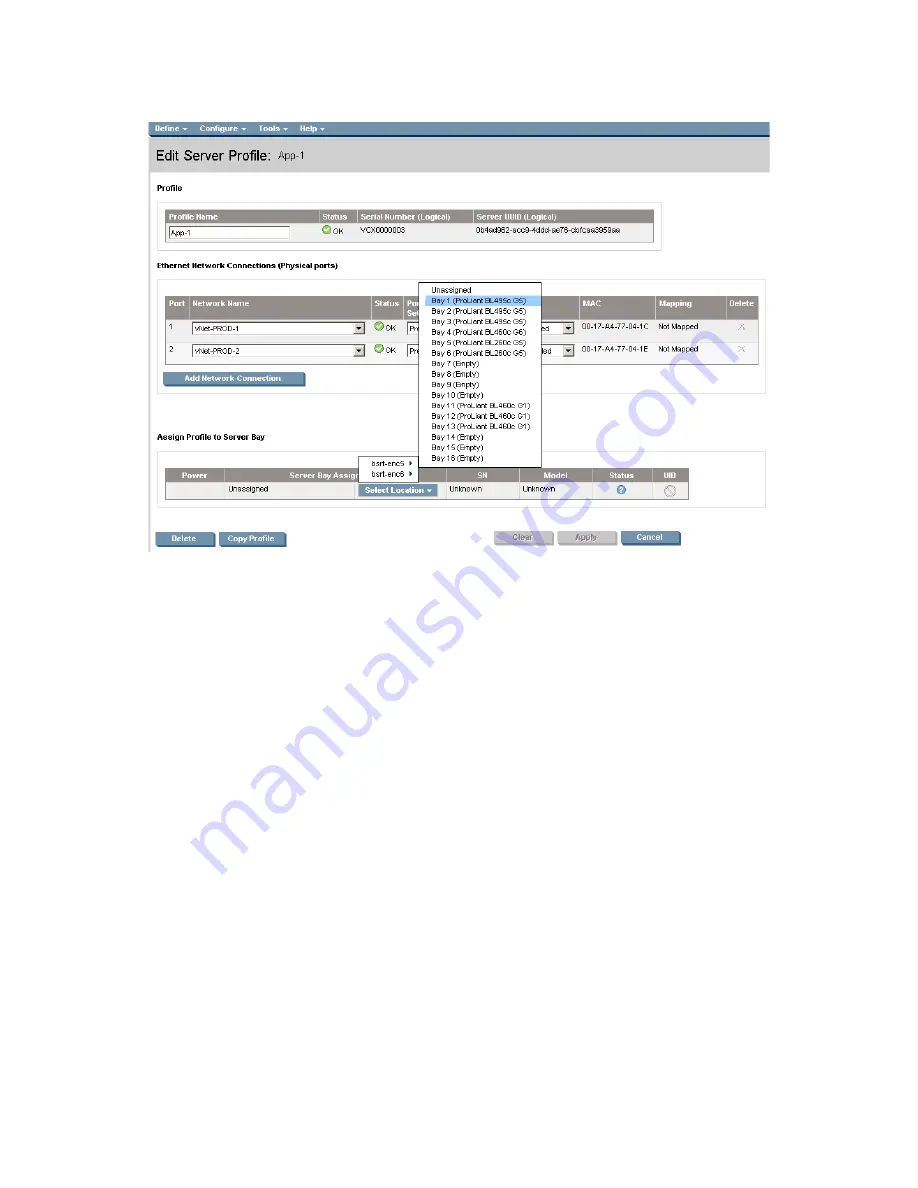
Define a Server Profile (App-1) and Assigns it to a Bay in either enclosure.
Summary
We created a Virtual Connect Domain within a BladeSystem c7000 enclosure, using 10Gb Ethernet
cables, we then connected the VC modules from a second enclosure to this enclosure. We then extended
the Virtual Connect domain (stacked) to include the second enclosure.
We created a Virtual Connect network (vNet) which provided additional bandwidth through LACP with
fail-over capabilities to uplinks on a from the second enclosure. One set of uplinks are will provide active
network connections while the second set of uplinks will be in standby mode to prevent any network
loops.
When VC profile App-1 is applied to the server in bay1 and is powered up, it has one NIC through each
module connected to “vNet-PROD”, which connects to the network infrastructure through the 1Gb uplinks.
These NICs could now be configured as individual NICs (figure 1-8) with their own IP address or as a
pair of TEAMED NICs (figure 1-9). Either NIC could be active. As a result, this server could access the
network through either NIC or either uplink cable, depending on which is active at the time. This server
profile could then be assigned to any valid server bay within the Virtual Connect stack.
As additional servers are added to the enclosure, simply create additional profiles, or copy existing
profiles, configure the NICs for vNet-PROD and apply them to the appropriate server bays.
Additional enclosures could be added to the stack by following the same instructions used to add the
second enclosure; up to four (4) enclosures can be stacked.


