7
65-0315—02
PAGE NAVIGATION
The Sola OI Displays present information and options in a
paged manner. Pages are displayed in a tree structure in
which the user navigates up and down to arrive at the desired
Function (see Fig. 8). The page descriptions are provided
below so that you can understand the purpose of each and
view the selections, parameters and information that is
available or required on each.
Common OI Display Page Symbols
Most pages have a Home button
on the top-left corner
of the screen and a Back button
on the top-right corner of
the screen. The Home button returns the user to the Home
page and terminates any operation in progress. The Back
button returns the user to the previous page.
Two other icons may be noticed on the top menu bar:
A Camera button
is for screen snapshot use. Up to 16
snapshots can be stored in the display and can be copied to a
USB memory stick.
A Padlock
indicates the operator is not currently logged
in (may have been timed out) and a password is needed to
change the setting. An unlocked padlock indicates the
password has been entered and the operator has successfully
logged into system.
This Padlock button also serves the purpose of allowing the
user to log in or log out of the system by pressing the button.
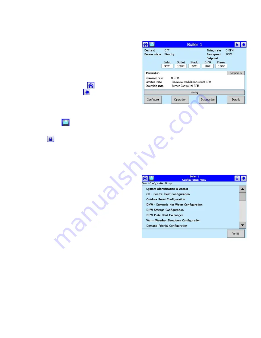
Status page
This status page appears on the S7999D when the Sola
control icon is pressed on the “Home” page. The status page
displays the current condition of the burner control and
displays some of the more important configuration settings.
The boiler name associated with the burner control is
displayed in the title on the status page.
NOTE: When the burner control has no boiler name
defined, Modbus address is used to identify the
boiler.
The initial status page displayed contains summary status
information as shown in Fig. 9. Any status information not
applicable for the installation is grayed/blanked out on the
screen.
Buttons on this screen include:
•
Configure
: used to configure the burner control (see
“Configure Button” for more details).
•
Operation
: used to perform daily or frequent functions with
the burner control, such as setpoint adjustment, etc. (see
“Operation Button” for details).
•
Diagnostic
: used to view burner control diagnostic
information (see “Diagnostics Button” for more details).
•
Details
: used to view burner control detail status
information (see “Details Button” for more details).
Fig. 9. Status summary page.
Configure Button
The configuration page allows the user to view and set
parameters that define how the connected Sola R7910
functions in the hydronic heating system or the R7911 steam
heating system.
The configuration page contains a menu of parameters
grouped into functional areas that the user selects for
configuration (see Fig. 8). See Table 60 for all parameters
available for configuration. If some parameters are not visible,
they have been made invisible by OEM’s application.
Fig. 10. Configuration menu page.
No specific order for configuration is required. All parameters
are enabled for editing, though some may not be applicable
(e.g., a configuration parameter may disable a control feature).
Selecting a parameter group from the menu displays
parameters exclusively applicable for the functional group on
the page (see Fig. 9). These parameters can be edited, and
when the user is finished, control returns back to the
configuration menu page.


