182
Complementary PWM mode
If channels 3 and 4 are combined, three-phase PWM output is possible with three pairs of
non-overlapping complementary waveforms.
Buffering
Input capture registers can be double-buffered. Output compare registers can be updated
automatically.
•
High-speed access via internal 16-bit bus
The 16-bit timer counters, general registers, and buffer registers can be accessed at high speed
via a 16-bit bus.
•
Fifteen interrupt sources
Each channel has two compare match/input capture interrupts and an overflow interrupt. All
interrupts can be requested independently.
•
Output triggering of programmable pattern controller (TPC)
Compare match/input capture signals from channels 0 to 3 can be used as TPC output triggers.
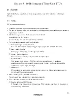
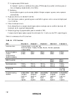
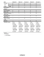
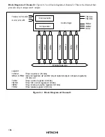
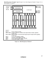
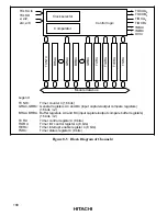
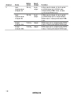
Table 8-1 summarizes the ITU functions.
Table 8-1 ITU Functions
Item
Channel 0
Channel 1
Channel 2
Channel 3
Channel 4
Clock sources
I nter nal cl ock s : ø, ø/
2,
ø/
4,
ø/
8
Ex ter nal cl ock s : TCLKA, TCLKB, TCLKC, TCLKD, selectable
independently
General registers
(output
compare/input
capture registers)
GRA0,
GRB0
GRA1,
GRB1
GRA2,
GRB2
GRA3,
GRB3
GRA4,
GRB4
Buffer registers
—
—
—
BRA3,
BRB3
BRA4,
BRB4
Input/output pins
TIOCA
0
,
TIOCB
0
TIOCA
1
,
TIOCB
1
TIOCA
2
,
TIOCB
2
TIOCA
3
,
TIOCB
3
TIOCA
4
,
TIOCB
4
Output pins
—
—
—
—
TOCXA
4
,
TOCXB
4
Counter clearing
function
GRA0/ GRB0
compare
match or
input
capture
GRA1/ GRB1
compare
match or
input
capture
GRA2/ GRB2
compare
match or
input
capture
GRA3/ GRB3
compare
match or
input
capture
GRA4/ GRB4
compare
match or
input
capture


