background image

92

―――――――――――――――――――――――――――――――――――――――

7.3 Basic Operational Procedures

―――――――――――――――――――――――――――――――――――

(5) Set the time axis range.

1. Press the

MENU/WAVE

key to display

the waveform screen.

2. Using the

CURSOR

keys and

,

keys, set the time axis
magnification/compression to "

×

1

".

(6) Begin measurement.

Press the

START

key. The

LED

above the key will light up

and then the measurement starts. The waveform will be
displayed on the screen simultaneously with triggering
occurs.

(7) End measurement.

When storage in the memory of 20 DIV of data is
completed, the

LED

goes out and the system enters to the

STOP condition, and the waveform is shown on the
screen.

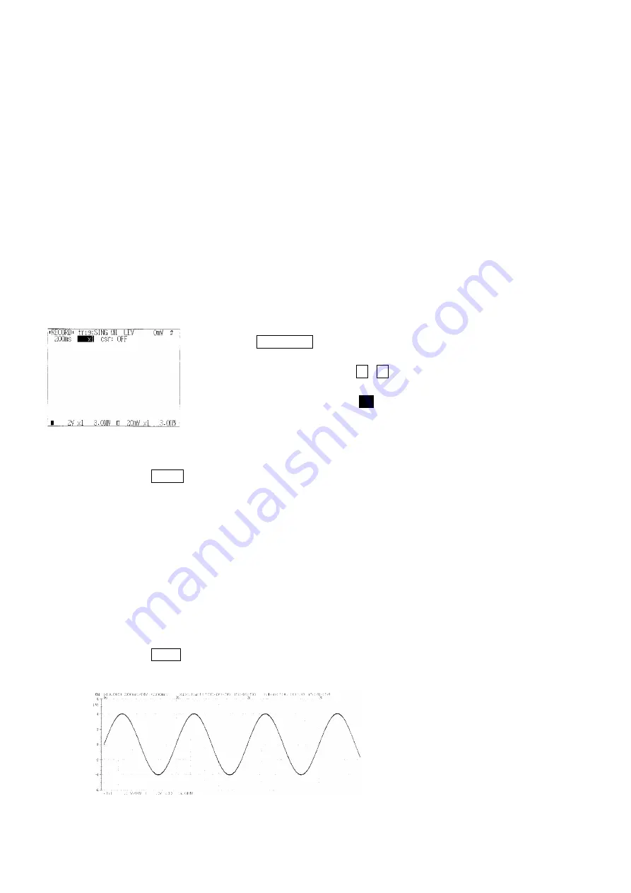
(8) Print out.

Press the

PRINT

key. The manual print as the figure

below is recorded.

Содержание 8804

Страница 1: ...MEMORY HiCORDER INSTRUCTION MANUAL 8804 ...

Страница 2: ......

Страница 3: ...pecifications 7 2 1 Main Units Specifications 7 2 1 1 General specifications 7 2 1 2 Trigger Unit 10 2 1 3 Memory Recorder Function 11 2 1 4 Recorder Function 12 2 1 5 RMS recorder function 13 2 1 6 X Y CONT Recorder Function 14 2 1 7 Auxiliary 15 2 1 8 A List of Optional Accessories 16 Chapter 3 Preparation and Setup 19 3 1 Setup 19 3 2 Loading Recording Paper 22 3 3 Care of Recording Paper 25 3 ...

Страница 4: ...ment 46 5 3 1 Measurement Starting and Stopping in the Three Trigger Modes 46 5 3 2 Stopping Measurement in the Memory Recorder Function 47 5 4 Printer Operations 48 5 4 1 Types of Recording and Functions 48 5 4 2 Setting the Style for Recording on the Printer Types of print 48 5 4 3 Recording on the Printer 50 5 4 4 Head Up and Paper End 53 5 4 5 Head Temperature Protection Function 53 5 5 Zero A...

Страница 5: ...play Screens 84 7 3 Basic Operational Procedures 89 7 3 1 Operational Flow 89 7 3 2 Example of Operation 91 Chapter 8 RMS Recorder Function Mode 93 8 1 What is the RMS Recorder Function 93 8 1 1 Introduction 93 8 1 2 Finding Reference Material in This Manual 94 8 2 Display Screens 97 8 3 Basic Operational Procedures 101 8 3 1 Operational Flow 101 8 3 2 Example of Operation 103 Chapter 9 X Y CONT R...

Страница 6: ...xternal Trigger 140 11 5 Internal and External Trigger Logical Operator 142 11 6 Trigger Modes Memory Recorder RMS Recorder Function 144 11 7 Pre Trigger Memory Rms Recorder Function 145 11 8 Trigger Timing 150 11 9 Timer Trigger 151 11 10 Level Meter Function 153 11 11 Trigger Output Terminal 154 Chapter 12 System Screen 155 12 1 What is the System Screen 155 12 2 Input Level Monitor Function Inp...

Страница 7: ...1 12 4 3 Self Check 174 Chapter 13 Input Units 179 13 1 Analog Inputs 179 13 2 Specifications 180 13 3 Safety Requirements 181 13 4 Input Cables 183 13 5 Measurement Errors Caused by Signal Source Internal Resistance 184 13 6 Logic Inputs 185 13 6 1 Logic Input Unit 185 13 6 2 Logic Probe 186 Chapter 14 Maintenance and Service 189 14 1 Changing the Battery 189 14 2 9420 BATTERY PACK 191 14 3 Recha...

Страница 8: ...Appendices APPENDIX 1 Apendix 1 Background APPENDIX 1 Apendix 2 Error Messages APPENDIX 5 Apendix 3 Glossary APPENDIX 6 Apendix 4 Example of Waveforms for Each Function APPENDIX 7 Index INDEX 1 ...

Страница 9: ... hand When the unit is delivered check and make sure that it has not been damaged in transit In particular check the accessories panel switches and connectors If the unit is damaged or fails to operate according to the specifications contact your dealer or HIOKI representative Accessories 9574 INPUT CORD 2 9232 RECORDING PAPER roll paper 1 Roll paper attachments 2 Instruction Manual 1 ...

Страница 10: ...age measurement incorrect measurement procedures could result in injury or death as well as damage to the equipment Please read this manual carefully and be sure that you understand its contents before using the equipment The manufacturer disclaims all responsibility for any accident or injury except that resulting due to defect in its product Safety ...

Страница 11: ...ions which it is particularly important that the user read before using the equipment Indicates a grounding terminal Indicates both DC Direct Current and AC Alternating Current Indicates DC Direct Current Safety symbols This Instruction Manual provides information and warnings essential for operating this equipment in a safe manner and for maintaining it in safe operating condition Before using th...

Страница 12: ...nt danger of accident resulting in death or serious injury to the user CAUTION Indicates that incorrect operation presents possibility of injury to the user or damage to the equipment NOTE Denotes items of advice related to performance of the equipment or to its correct operation The following symbols are used in this Instruction Manual to indicate the relative importance of cautions and warnings ...

Страница 13: ...imum input voltage Analog input 500 V DC AC peak EXT TRIG 5 V to 10 V TRIG OUT 20 V to 30 V 500 mA max 200 mW max When using an AC adapter always use the specified 9418 10 AC ADAPTER PSA 30U 120 PHIHONG The rated supply voltage is 100 to 240 VAC Voltage fluctuations of 10 from the rated supply voltage are taken into account The rated supply frequency is 50 60 Hz Do not use a power supply that fall...

Страница 14: ... To avoid damage to the unit do not input a voltage current exceeding the rated maximum to the external input terminals The optimal operating temperature and humidity range of the unit is 5 to 40 and 35 to 80 RH or less Do not use the unit in direct sunlight dusty conditions or in the presence of corrosive gases NOTE 1 Before Powering On Check that the correct 9418 10 PSA 30U 120 PHIHONG 9420 or L...

Страница 15: ... Using recording paper of a different specification may not only result in impaired printing quality but even prevent the printer from operating Always use the 9232 RECORDING PAPER 4 Storage If the unit will not be used for a substantial period to protect the printer head and prevent deformation of the rubber rollers move the head up down lever to the head up position If the unit is left in the st...

Страница 16: ... measurement ranges Chapter 3 Preparation and Setup Describe preparation and setup for using the unit loading recording paper and important points to note during measurement Chapter 4 Screen Displays and Settings Describe screen displays and principal basic key operations Chapter 5 Basic Operation Describe the method of operation settings start and stop measuring and printer operation which is com...

Страница 17: ...ions Describe the settings of trigger functions and how to use them Chapter 12 System Screen Describe the system screen and details of special function setting the scaling function self check function and other functions Chapter 13 Input Units Describe the input units including specifications and important notes on operation Chapter 14 Maintenance and Service Describe maintenance replacement of co...

Страница 18: ... 10 Front View 1 2 3 Names and Functions of Parts FEED key While pressing this key the recording paper is fed forward PRINT key Press this key to print out the waveform stored in memory COPY key Press this key to print a copy of the current screen display ...

Страница 19: ... about 20 seconds with the backlight on the backlight automatically goes off keys Press this key to select the measurement condition Press the SHIFT key the waveform scrolling is possible MENU WAVE key Press this key to change the screen display CURSOR keys These four keys move the flashing portion on the screen display the flashing cursor up down left and right Press the SHIFT key to move the A a...

Страница 20: ...e the input terminals for the logic inputs and are only to be used with the optional logic probes A maximum of two logic probes can be connected CH A CH B Analog input terminals These are input terminals for analog inputs non balanced input type CH 1 CH 2 H High level input L Low level input ...

Страница 21: ...key to turn the power supply on and off Protective grounding terminal GND Connect to ground AC adapter connecting terminal Use the specified 9418 10 AC ADAPTER PSA 30U 120 PHIHONG EXT TRIG TRIG OUT terminals These terminals can be used to synchronize a number of the 8804 units for parallel operation ...

Страница 22: ...xiv Names and Functions of Parts 19 Bottom View 19 Battery compartment Six LR6 alkaline batteries or the 9420 can be installed ...

Страница 23: ...compact and light it is highly portable The 8804 is also extremely convenient as a portable unit since it can be powered either through an AC adapter or by batteries 2 Analog inputs and logic inputs A 8 channel logic input unit is fitted The logic inputs all have a common ground with the main unit The data for 2 channels of analog inputs and 8 channels of logic inputs can be simultaneously display...

Страница 24: ...he rms value 6 High powered trigger capability A digital trigger circuit is used Many and various settings are available with functions such as trigger level trigger slope or trigger filter or types such as window out trigger or any other digital function The trigger operation is possible at voltage drops in commercial power supplies and varying the rms value 7 Quick and easy to see waveform refer...

Страница 25: ... 6 7 8 9 10 11 12 13 14 15 APP IND 10 Scaling function By setting the physical amount of input signal and the name of the units used it is possible to convert measured data which are obtained as voltage values into values in set units ...

Страница 26: ...input units Each channel uses a separate power source which is completely electrically insulated from the main 8804 unit 3 The A D converted data is recorded in memory under control of the memory controller circuit 4 The 8804 main unit employs a digital trigger circuit and in the case of an internal trigger generates a trigger signal by comparing the digital value after A D conversion with a set v...

Страница 27: ...IND Analog input units 8 bit CPU LCD Logic inputs Printer Total 2 probes Control panel Logic probes Memory control and Trigger circuit Storage memory 64 K words Photo coupler Photo coupler Analog input A D Analog input A D Logic probes Total 2 probes Block Diagram ...

Страница 28: ...6 1 2 System Operation ...

Страница 29: ... channels are both standard equipment for the 8804 Memory capacity 64 K words Analog 9 bits logic 4 channels 64 K words channel when channel 1 is in use Analog 9 bits logic 4 channels 32 K words channel when both channel 1 and 2 are in use Maximum sampling speed 400 kS s All channels simultaneously Time axis accuracy 0 01 difference between grid and actual time Operating temperature and humidity r...

Страница 30: ...ly voltage of the AC adapter is 100 to 240 VAC Voltage fluctuations of 10 from the rated supply voltage are taken into account Rated supply frequency is 50 60 Hz Six LR6 alkaline batteries are used The AC adapter is prior to batteries when using together 9420 BATTERY PACK can be used Maximum rated power 20 VA max when using the AC adapter 15 VA max when using the batteries Charging function The 94...

Страница 31: ...hstands 5 107 pulses 25 printing duty factor Wear endurance at least 30 km Recording paper Roll type thermosensitive recording paper 74 mm 10 m Recording width Total recording width 72 mm 576 dots Waveform portion 60 mm f s 1 DIV 10 mm 6 DIV f s Recording speed Approx 2 s cm max Paper feed accuracy 3 Display Screen Approx 4 9 inch LCD display 320 240 dots Dots spacing 0 31 0 31 mm ...

Страница 32: ...d the time interval can be set Trigger condition Logical AND or OR of each trigger source Types of trigger analog Level trigger window out trigger rms value level trigger voltage drop trigger for commercial power supplies Types of trigger logic Pattern trigger specified by 1 0 and means that either 1 or 0 is fine Trigger filter Available The amount of filter setting possible Trigger level resoluti...

Страница 33: ...y line display for the SINGLE and DUAL Waveform magnification and compression ratio 10 5 2 1 1 2 1 5 1 10 1 20 1 50 1 100 along the time axis 4 2 1 1 2 along the voltage axis Waveform scrolling Available in both the left right and the up down directions For the scrolling of up down direction change the zero position Roll mode ON OFF Operating in 20 ms DIV to 2 min DIV Auto print ON OFF It automati...

Страница 34: ... Interpolation function Line display only Waveform magnification and compression ratio 1 1 2 1 5 1 10 1 20 1 50 along the time axis 4 2 1 1 2 along the voltage axis Waveform recording Memorize and hold the last 200 DIV Auto print ON OFF Print the memorized waveform automatically 200 500 ms DIV 1 s DIV are only displayed on the screen Manual print Available Partial print Print between the A and B c...

Страница 35: ...00 DIV CONT Screen print format SINGLE DUAL Interpolation function Line display only Waveform magnification and compression ratio 1 1 2 1 5 1 10 1 20 1 50 along the time axis 4 2 1 1 2 along the voltage axis Waveform recording Memorize and hold the last 200 DIV Auto print ON OFF It automatically prints the memorized waveform 200 500 ms DIV 1 s DIV are only displayed on the screen Manual print Avai...

Страница 36: ...ot 2 5 kS s max line Effective recording dimensions 60 mm 60 mm 6 DIV 6 DIV with the printer Recording time Unlimited Interpolation function Available dot line Superimposition Available Monitor function Monitor display on screen Print function Manual printing screen copy 2 1 6 X Y CONT Recorder Function ...

Страница 37: ...umerical calculation function Maximum value minimum value peak value average value rms value area value Cursor read out Available Waveform back up function Available Setting condition storing function Available up to 4 Save the setting condition in file format Starting status backup function Available Screen back lighting ON OFF Go OFF automatically when using the battery pack or LR6 alkaline batt...

Страница 38: ... dia mini plug approx 1 5 m 9306 LOGIC PROBE 4 channels detects the ON OFF state of a digital contact signal 9307 LINE TYPE LOGIC PROBE Floating 4 channels detects the ON OFF state of an AC DC voltage 9010 CLAMP ON PROBE 10 to 500 A 40 Hz to 1 kHz 9018 CLAMP ON PROBE 10 to 500 A 40 Hz to 3 kHz 9132 CLAMP ON PROBE 20 to 1000 A 40 Hz to 1 kHz 9270 CLAMP ON SENSOR 20 A 5 Hz to 50 kHz 9271 CLAMP ON SE...

Страница 39: ...nits Specifications 1 2 3 4 5 6 7 8 9 10 11 12 13 14 15 APP IND NOTE The 9270 to 9272 CLAMP ON SENSORs and the 9277 to 9279 UNIVERSAL CLAMP ON CTs are used with the 9555 SENSOR UNIT They cannot be used by themselves ...

Страница 40: ...18 2 1 Main Units Specifications ...

Страница 41: ...ine batteries Do not use old and new batteries or batteries of different types together The manufacturer disclaims all responsibility for any accident or injury except that resulting due to defect in its specified batteries or battery packs The 9420 are used in sets of three Do not use with batteries together Do not use old and new batteries or batteries of different types together If intend to pe...

Страница 42: ...is state for an extended period of time the battery pack may be discharged too much Be sure to turn OFF the power switch on the unit When the battery capacity is reduced the power is automatically turned off Before turning on the power again with AC adapter or new batteries turn the power off and leave for about 30 seconds When not in use for a long time to prevent possible corrosion caused by bat...

Страница 43: ... if a grounded power plug cannot be used connect the unit to a proper ground Be sure to ground the 8804 properly even when using batteries 4 Environment for use The operating temperature and humidity range for the 8804 is 5 to 40 and 35 to 80 RH Also do not expose the unit to direct sunlight dust or corrosive gas ...

Страница 44: ...nts 3 2 Loading Recording Paper 1 Pull the stock cover to open 2 Raise the head up down lever 3 Insert the attachments into the hole of the roll of 9232 RECORDING PAPER Insert the leading edge of the paper from under into the gap behind the printer roller and pull it out upward ...

Страница 45: ... quite straight There is a possibility of a paper jam if the recording paper is slanted against to the roller Be sure to set the paper correctly 5 Put down the head up down lever 6 Pull the recording paper to the outside through the printer exit slot in the stock cover 7 Close the stock cover and finish by tearing off the recording paper at the edge of the printer exit slot ...

Страница 46: ...d the printed characters may become uneven If the recording paper is set in back to front by mistake the waveform cannot be drawn Make sure to set the paper correctly This unit uses a thermal printer The recording paper supplied has characteristics finely tuned for use with the printer Using recording paper of a different specification may not only result in impaired printing quality but even prev...

Страница 47: ... careful not to leave the roll paper in strong light The recording paper uses a thermochemical reaction Note the following points To avoid discoloration do not leave recording paper in direct sunlight Store at not more than 40 and 90 RH or less To keep definitive data make photocopies of the recordings Thermal paper changes color if it comes into contact with organic solvents such as alcohols este...

Страница 48: ...aximum floating voltage for the analog inputs is 450 V AC DC In order to avoid an electric shock accident and damage to the unit do not input voltage in excess of these limitations either between any two channels or between a channel and the main unit WARNING The logic inputs and the 8804 have a common ground When measuring input which has different reference potential beware of electric shock 3 4...

Страница 49: ...aveform status and trigger and there are also three system screens The Memory recorder function mode also has a numerical calculation screen 1 The status stts screen The general settings such as time axis and recording length can be set 2 The trigger trig screen The trigger condition can be set 3 The waveform screen This is the screen for displaying the measurement results The main setting items c...

Страница 50: ...reen and Page 2 screen Input level monitor screen displays level monitor In page 1 screen system variable comment setting and clock setting are performed In page 2 screen scaling saving the setting condition and each checking are performed 5 The numerical calculation screen Memory recorder The numerical measurement is performed ...

Страница 51: ...n XY CONT Status Screen XY CONT Trigger Screen System Input Level Monitor Screen System Page 1 Screen System Page 2 Screen Press the MENU WAVE key and the screen displays change in the arrow direction Press the key after moving the flashing cursor to the function item the function changes in the lower direction and also press key the function changes in the upper direction Press the key after movi...

Страница 52: ...us page Press the START key the measurement will start on any screen except the system screen and changes to the waveform screen Method 1 Using the CURSOR keys move the flashing cursor to the function item 2 Select the function by using the and keys These functions are basic measurement function and there are the Memory recorder Recorder RMS recorder and X Y CONT recorder functions Turn on the pow...

Страница 53: ...the screen of setting item 2 Using the CURSOR keys move the flashing cursor to the item to be set 3 Using the keys select or change the settings When making a setting on the screen except the waveform screen the selectable setting contents are displayed on the lower screen On the waveform screen if the SHIFT key is pressed the SHIFT mark indication the setting can not be changed by using the CURSO...

Страница 54: ...ENU WAVE key and select the status screen stts 2 Set the function to RECORD 1 Using the CURSOR keys move the flashing cursor on the function item 2 By using the and keys select RECORD 3 Set the time axis range to 5 s DIV 1 Using the CURSOR keys move the flashing cursor to time 2 By using the and keys set to 5 s DIV ...

Страница 55: ...o CONT 1 Using the CURSOR keys move the flashing cursor to shot 2 By using the and keys set to CONT 5 Set the screen setting to single SINGLE 1 Using the CURSOR keys move the flashing cursor to format 2 By using the and keys set to SINGLE Set the rest of items following the same procedures above ...

Страница 56: ...etting format 5 Frequency 6 Waveform clear 7 Line style 8 Channel information 9 Waveform display 10 Voltage axis X Y axis range 11 Input coupling 12 Magnification compression along the voltage axis range 13 Position 14 Filter 15 Trigger setting 16 Print types 17 Roll mode 18 Automatic printing 19 Numerical calculation 20 Zero adjust 5 2 Basic Setting Items of Each Function setting possible cannot ...

Страница 57: ...1 10 1 20 1 50 1 Time axis range Show the time interval along the time axis direction for 1 DIV a scale of the recording paper In the Memory recorder function the sampling period is 1 80th of the set value for the time axis range 2 Magnification compression along the time axis Set the magnification compression ratio along the time axis By magnifying the waveform detailed observations is possible B...

Страница 58: ...tion 10 1 2 Selection Memory recorder 20 50 100 200 400 DIV channel 1 2 800 DIV channel 1 only Recorder RMS recorder 20 50 100 200 400 DIV CONT 3 Recording length The length of recording for one measurement operation number of DIV can be set ...

Страница 59: ...r showing input signal waveforms on the screen display and recording them on the printer The styles SINGLE and DUAL are available X Y DOT and X Y LINE are available only in the Memory recorder function 1 SINGLE Display and record as one graph 2 analog signals and 8 logic signals max 2 DUAL Display and record as two graphs on each graph an analog signal and 4 logic signals max Input waveform for ch...

Страница 60: ...hannel 2 is Y axis Display and record as one graph The difference between X Y DOT and X Y LINE is whether linear interpolation is performed or not 5 Frequency RMS recorder only Set the frequency of commercial power supplies 50 60 Hz 6 Waveform clear X Y CONT recorder only It sets whether clear the waveform or not when pressing the START key to start measurement and the previous waveform is left If...

Страница 61: ...ETTING It displays the setting items such as waveform displays and the voltage axis range of the input UP LOW It displays the range of the voltage value Upper and lower limit value SETTING UP LOW 7 Line style X Y CONT recorder only It sets to display and record the input signal the sampled data either just as it is or after subjecting it to linear interpolation 8 Channel information It displays th...

Страница 62: ...S recorder 20 50 100 200 500 mV DIV 1 2 5 10 20 50 V DIV Selection Flashing cursor 9 Waveform display It sets the channel to be displayed or recorded to ON or OFF 10 Voltage axis X Y axis range Set the voltage value for 1 DIV along the voltage axis direction vertically The channel 1 is shown along the X axis and the channel 2 is shown along the Y axis at X Y plot ...

Страница 63: ...ured GND The input signal is not connected This allows the zero position to be checked Selection Flashing cursor Memory recorder Recorder RMS recorder 4 2 1 1 2 Selection Flashing cursor 11 Input coupling It sets the coupling condition of the input signal 12 Magnification compression along the voltage axis range For each channel set the magnification compression ratio along the voltage axis ...

Страница 64: ... selections When the position setting is 3 DIV 0 V appears at the center of the screen 50 position When the magnification compression ratio is set to 1 if set the position to 0 DIV 0 V appears at the 0 position of the screen and if set the position to 6 DIV 0 V appears at the 100 position of the screen The range for the position varies according to the magnification compression ratio along the vol...

Страница 65: ... Display 3 DIV 6 DIV Xaxis 0 256 0 V 0 256 0 V 511 Display Display NOTE The position has the significance shown in the figure below It is possible to display the hidden portion of the waveform according to the relative position of the displayed section at which 0 V appears In the X Y CONT recorder function since the time axis waveform for each channel is not stored even if the position is changed ...

Страница 66: ...ents and noise in the signal can thicken the recording line 2 The case in which the recording line becoming thick because ripples are present in the output such as transducers 3 Pulse type noise in the RMS recorder function 15 Trigger setting Refer to Chapter 11 Trigger Function to find out about the trigger setting 16 Print types Set either print out the measured data in waveform or in numerical ...

Страница 67: ...to the printer Refer to Section 5 4 3 Recording on the Printer 19 Numerical calculation Memory recorder only It is possible to calculate the waveform data Refer to Section 6 7 Numerical Calculation 20 Zero adjustment It adjusts the waveform position at the position value when the input voltage is 0 V Refer to Section 5 5 Zero Adjustment ...

Страница 68: ... 1 When the trigger mode is SINGLE Press the START key and if the trigger conditions hold an amount of data of length equal to the recording length will be read in and stored Without pressing the STOP key the system will go into the measurement finished state 2 When the trigger mode is REPEAT Press the START key and if the trigger conditions hold an amount of data of length equal to the recording ...

Страница 69: ... the waveform data in the range which the setting of the time axis range is more than 20 ms DIV even if the STOP key is pressed the LED above the START key is illuminated and measurement operation continues until reading in and storage of waveform data has finished If the time axis range is 20 ms DIV or less the waveform is displayed to the sampled point When setting the trigger mode to REPEAT or ...

Страница 70: ...of Recording and Functions 5 4 2 Setting the Style for Recording on the Printer Types of print Can be executed Cannot be executed While printing out the back light forcibly goes off There are two styles of recording on the manual and partial print waveform WAVE and numerical values LOGGING Either of these can be selected In the X Y CONT recorder function the recording as numerical values is not po...

Страница 71: ...status screen 1 Move the flashing cursor to prt kind 2 By using the and keys select WAVE or LOGGING 3 When LOGGING is selected in step 2 move the flashing cursor to interval and set the data sampling interval to be printed out 1 DIV equals to 80 samples In the Recorder and RMS recorder function however the maximum and minimum values are saved in memory as data the maximum value is printed out as n...

Страница 72: ...the PRINT key The A and B cursors displayed on the screen are not printed The recording as numerical values can not be performed in the X Y CONT recording function Pressing the FEED key except during measuring the recording paper is fed 2 Partial printing Memory recorder Recorder RMS recorder function Using the A and B cursors print out only the desired portion of the entire length of the recordin...

Страница 73: ...r to Section 6 5 Roll Mode Function 3 Auto print Memory Recorder RMS recorder function When the view is enlarged along the voltage axis printouts on the printer will also be enlarged in the same manner The auto printing can be used for both waveform printing WAVE and numerical printing LOGGING After reading the waveform data the data is automatically printed out Memory recorder Printing out simult...

Страница 74: ...if the printing interval is set to less than 80 at the start of auto printing auto print ON the following warning message appears and the interval is forcibly set to 80 WARNING 23 Can t set interval to 1 40 4 Screen copy printing all function It is possible to make a direct hard copy of the screen display when in the waveform screen status screen trigger screen or system screen Method Press the CO...

Страница 75: ...n circuit This cuts out operation of the printer if the head temperature reaches a certain level It is therefore possible for the printer to stop operating while in use and temporarily feed blank paper The tendency of the head temperature to rise is exacerbated by a greater black area being printed and by a faster paper feed speed Additionally higher ambient temperatures make it more likely that t...

Страница 76: ...for reading precise values from the screen a printed recording or to ensure accurate results from waveform computations Method on the status screen 1 Using the CURSOR keys move the flashing cursor to 0 adjust 2 Press the START key Zero adjustment should be performed after about 30 minutes of warm up at the powering on Zero adjustment cannot be performed while measurement is taking place ...

Страница 77: ...mber of useful ways become possible 1 Once an input signal has been stored in the memory it can be displayed and recorded 2 Recording can be performed for all input channels along the same time axis Allowing the signals to overlap makes it easier to see their relative relationships 3 The maximum sampling speed is 400 kS s 4 The maximum recording capacity recording length is 64 K words divided by t...

Страница 78: ...s possible to extract and print only the section which one desires to see 9 Reprinting is available Once a waveform has been recorded it can be printed as many times as desired 10 With the pre trigger function it is possible to inspect the signal before the trigger point 11 The conversion to the X Y waveform plot is possible 12 With the calculation functions a captured waveform can be analyzed 1 B...

Страница 79: ...er to Section 5 5 Zero Adjustment This function provides for accurate adjustment of the waveform to the origin position when a zero voltage is input 5 A and B cursors operations Refer to Section 10 1 Using the A and B Cursors The time differences frequencies and voltage differences getting a direct digital can be readout on the waveform screen 6 Waveform scrolling function Refer to Section 10 2 Wa...

Страница 80: ...rigger can be used as the internal trigger 12 Numerical calculation function Refer to Section 6 7 Numerical Calculation Waveform parameter calculation can be performed 13 Scaling function Refer to Section 12 4 1 Scaling Function The scaling function allows the units and numerical values for the input voltages to be converted so that they can be directly read out as physical values of the parameter...

Страница 81: ...alue for the time axis range 3 Recording length 20 50 100 200 400 DIV channel 1 2 800 DIV ch 1 only The length of recording for one measurement operation the number of DIV can be set 4 Roll mode OFF ON Display simultaneously with waveform reading 5 Screen setting SINGLE DUAL X Y DOT X Y LINE Set the style for displaying waveforms on the waveform screen and recording them on the printer 6 Types of ...

Страница 82: ...ange 20 50 100 200 500 mV DIV 1 2 5 10 20 50 100 V DIV Set the voltage axis range for each channel 12 Input coupling V DC GND Select the connection for the input 13 Magnification compression along the voltage axis 4 2 1 1 2 Set the magnification compression ratio along the voltage axis for each channel 14 Position 0 4 to 6 4 DIV magnification ratio 1 Set the position for each channel 15 Filter OFF...

Страница 83: ...μs DIV 1 2 5 10 20 50 100 200 500 ms DIV 1 2 5 10 30 s DIV 1 2 min DIV Set the time for 1 scale 1 DIV The sampling period is 1 80th of the set value for the time axis range 5 Magnification compression along the time axis 10 5 2 1 1 2 1 5 1 10 1 20 1 50 1 100 Set the magnification compression ratio along the time axis 6 A and B cursors OFF The A and B cursors can be used 7 Waveform display OFF ON S...

Страница 84: ... 1 2 Set the magnification compression ratio along the voltage axis for each channel 11 Position 0 4 to 6 4 DIV magnification ratio 1 Set the position for each channel NOTE By level meter function Refer to Section 11 10 Level Meter Function the level of the analog input signal is displayed on the waveform screen during waiting for the trigger ...

Страница 85: ...IP Set the internal trigger 4 External trigger OFF ON Using of the external input as a trigger source is possible 5 Trigger mode SINGLE REPEAT AUTO Select whether to stop after a single recording or carry out repeated recording 6 Pre trigger 0 5 10 25 50 75 90 95 100 95 Set the proportion in percent of the recording length of the signal that comes before the trigger 7 Timer trigger OFF ON Used whe...

Страница 86: ...edures 6 3 1 Operational Flow The flowchart below illustrates the sequence of operations involved in using the memory recorder function Set to the Memory recorder function mode Set the input and storage speed for the input signal waveform Set the length of the recording for one measurement Like the recorder function in time axis range less than 20 ms DIV the waveform can be scrolled Set the format...

Страница 87: ... will be sent to the printer as a waveform or as numerical values Set whether or not printing will occur simultaneously with screen display Set the channels for which display and recording will be performed Also set voltage axis range magnification compression along the voltage axis range input coupling and filters Set the trigger source the trigger type and conditions and the pre trigger Press th...

Страница 88: ...804 2 Connect the input Connect the oscillator to the input terminal of channel 1 of the 8804 Set the oscillator so that it outputs a sine wave of frequency 1 kHz and voltage of 8 Vp p 3 Set the status screen 1 Using the CURSOR keys and keys set as same as the setting on the figure left 4 Set the trigger screen 1 Press the MENU WAVE key to display the trigger screen 2 Using the CURSOR keys and key...

Страница 89: ...time axis magnification compression to 1 6 Begin measurement Press the START key The LED above the key will light up and then the measurement starts 7 End measurement When storing in the memory of 20 DIV of data is completed the LED goes out and the system enters the STOP condition and the waveform is shown on the screen 8 Print out 1 Press the COPY key The display copy as the figure left is recor...

Страница 90: ...68 6 3 Basic Operational Procedures 2 Press the PRINT key The manual print as the figure below is recorded ...

Страница 91: ...en 1 Press the left and right CURSOR keys simultaneously and then press the START key 2 After setting the range the LED above the START key will light up and then the measurement is automatically started If there is only a small difference between maximum value and the minimum value in the range of highest sensitivity for the channel 1 the setting is made to the time axis for the channel 2 If the ...

Страница 92: ... 1 and 2 trigger level value Set automatically Input filter and input coupling Set to OFF V DC Trigger type slope and filter Set to level rising or OFF External trigger and timer trigger Set to OFF Trigger mode Set to AUTO Pre trigger Set to 10 Magnification compression ratio along the time and voltage axes Set to 1 ...

Страница 93: ...of data has been completely sampled during low speed sampling it takes a long time to complete the printing If roll mode is enabled ON after triggering it is possible to start waveform display and print by the auto print simultaneously with the capturing waveform just as during operation in the Recorder function mode Method on the status stts screen 1 Using the CURSOR keys move the flashing cursor...

Страница 94: ...s shown as X axis and the channel 2 is shown as Y axis Magnification and compression along the voltage axis are also effective for X Y plots Using the A and B cursors the X Y plot can be made for the data between the A and B cursors X Y DOT X Y LINE Display and record as one graph The difference between X Y DOT and X Y LINE is whether the linear interpolation is performed or not Refer to Section 5...

Страница 95: ...g the CURSOR keys move the flashing cursor to format 2 By using the and keys set to X Y DOT or X Y LINE On the X Y DOT and X Y LINE screens the following items can be set Function Trigger mode Internal trigger Time axis range A B cursors X and Y axes range Input coupling Magnification compression along the X and Y axes range Position ...

Страница 96: ...of these types of calculation appears as a numerical value If the A and B cursors are not being used the calculation is performed for all of the data When the cursors are used the calculation is performed for the data between the A and the B cursors The settings relating to the calculation functions are made on the numerical calculation screen On the status stts screen 1 Move the flashing cursor t...

Страница 97: ... or OFF whether the results of calculation is printed out or not by pressing the or keys 3 Using the CURSOR keys move the flashing cursor to No 1 to No 4 Select the types of calculation by pressing the and keys Up to four calculations can be set simultaneously 4 Case A When the calculation is performed simultaneously with the waveform reading Press the START key Case B When the calculation is perf...

Страница 98: ...aveform screen the waveform and results of the calculation are displayed together The results is automatically recorded on the printer when print setting is ON The calculation can be performed as many times as desired on the reading waveform data ...

Страница 99: ...alue Min The minimum value of the waveform data is shown in volts Time to minimum value Min Time The time period from the moment that triggering occurred till the minimum value is attained is shown in seconds If the minimum value is attained twice or more in the data the first point is took as the minimum value 3 Peak to peak value The peak to peak value the difference between the maximum value an...

Страница 100: ...point corresponding to 0 V to the signal waveform is shown in volt seconds If the A and B cursors are in use the area between A and B cursors is displayed The equation used for the calculation is as follows n the number of data samples di the ith data value of the source channel h Δt sampling period If scaling has been set calculation will be executed after scaling the waveform data When scaling t...

Страница 101: ...V 12 5 0 8 s 2 25 1 6 s 5 62 5 4 s 10 125 8 s 20 250 16 s 50 625 40 s 100 1 25 ms 1 min 20 s 200 2 5 2 min 40 s 500 6 25 6 min 40 s 1 s DIV 12 5 13 min 20 s 2 25 26 min 40 s 5 62 5 1 h 6 min 10 125 2 h 13 min 30 375 6 h 40 min 1 min DIV 750 13 h 20 min 2 1 5 s 26 h 40 min NOTE 6 8 Memory Recorder Function Possible Recording Time Calculated with recording length 800 DIV only channel 1 is in use ...

Страница 102: ...80 6 8 Memory Recorder Function Possible Recording Time ...

Страница 103: ... signals to overlap makes it easier to see their relative relationships 3 The chart speed time axis scale can be set to any of 13 levels from 200 ms DIV to 1 h DIV 200 ms to 1 s DIV for display only 4 High speed sampling Because sampling can be done at speeds of 2 5 μs independently of the printing speed envelope observation is possible 5 The waveform can be scrolled While continuous real time rec...

Страница 104: ...tage axis range input coupling magnification compression along the voltage axis range position and filter 2 Start stop measurement operation Refer to Section 5 3 Starting and Stopping Measurement Measurement is started by pressing the START key and finished by pressing the STOP key 3 Printing function Refer to Section 5 4 Printer Operations There are two styles of recording waveform WAVE and numer...

Страница 105: ...creens display format to select 8 Channel information function Refer to Section 5 2 Basic Setting Items of Each Function 8 9 Trigger function Refer to Chapter 11 Trigger Function The suitable trigger can be selected from the many types of trigger available Level trigger window out trigger and logic trigger can be used as the internal trigger 10 Scaling function Refer to Section 12 4 1 Scaling Func...

Страница 106: ...0 CONT The length of recording for one measurement operation the number of DIV can be set 4 Screen setting SINGLE DUAL Set the style for displaying waveforms on the waveform screen and recording them on the printer 5 Types of print WAVE LOGGING Select the style for recording on the printer 6 Print interval 1 8 16 40 80 160 400 800 1600 When recording as numerical value set the printing interval 7 ...

Страница 107: ...elect the connection for the input 12 Magnification compression along the voltage axis 4 2 1 1 2 Set the magnification compression ratio along the voltage axis for each channel 13 Position 0 4 to 6 4 DIV magnification ratio 1 Set the position for each channel 14 Filter OFF 500 Hz 5 Hz Set the low pass filters to restrict the frequency bands 15 Zero adjustment 0 adjust Performs the zero adjustment ...

Страница 108: ...display only 2 5 10 30 s DIV 1 2 5 10 30 min DIV 1 h DIV Set the chart speed Set the time for 1 scale 1 DIV 5 Compression along time axis 1 1 2 1 5 1 10 1 20 1 50 Set the compression ratio along the time axis for each channel 6 A and B cursors OFF The A and B cursors can be used 7 Waveform display OFF ON Select whether display waveforms or not 8 Voltage axis range 20 50 100 200 500 mV DIV 1 2 5 10...

Страница 109: ...2 Set the magnification ratio along the voltage axis for each channel 11 Position 0 4 to 6 4 DIV magnification ratio 1 Set the position for each channel NOTE With the level meter function the level of the analog input signal is displayed on the waveform screen during waiting for the trigger Refer to Section 11 10 Level Meter Function ...

Страница 110: ...IC Set the internal trigger 4 External trigger OFF ON Using of the external input as a trigger source is possible 5 Trigger mode SINGLE REPEAT Select whether to stop after a single recording or carry out repeated recording 6 Trigger timing START STOP Set whether start or stop recording after the trigger occur 7 Timer trigger OFF ON Use when recording at a predetermined time is required 3 Trigger s...

Страница 111: ...ding length shot Set the time axis range time Connect the inputs 7 3 Basic Operational Procedures 7 3 1 Operational Flow The flowchart below illustrates the sequence of operations involved in using the recorder function Set to the Recorder function mode Set the chart speed Set the length of the recording for one measurement Set the format type for the waveform display screen ...

Страница 112: ...as a waveform or as numerical values Set whether printing will occur simultaneously with screen display or not Set the channels for which display and recording will be performed Also set voltage axis range magnification compression along voltage axis range input coupling and filters Set the trigger source trigger type and conditions and trigger timing Press the START key and start measurement Prin...

Страница 113: ... power switch of the 8804 2 Connect the input Connect the oscillator to the input terminal of channel 1 of the 8804 Set the oscillator so that it outputs a sine wave of frequency 1 Hz and voltage of 8 Vp p 3 Set the status screen 1 Using the CURSOR keys and keys set as same as the setting on the figure left 4 Set the trigger screen 1 Press the MENU WAVE key to display the trigger screen 2 Using th...

Страница 114: ...ss the START key The LED above the key will light up and then the measurement starts The waveform will be displayed on the screen simultaneously with triggering occurs 7 End measurement When storage in the memory of 20 DIV of data is completed the LED goes out and the system enters to the STOP condition and the waveform is shown on the screen 8 Print out Press the PRINT key The manual print as the...

Страница 115: ...d as the rms value 1 Real time continuous recording is possible 2 The 8804 is designed to measure commercial power supplies 50 60 Hz and DC signal The chart speed time axis scale can be set to any of 9 levels from 5 s DIV to 1 h DIV 3 There are two display formats to choose from SINGLE and DUAL of time axis waveforms are available 4 Recording can be performed for all input channels along the same ...

Страница 116: ...memory 200 DIV including the display screen can be printed as many times as desired 8 With the pre trigger function the signal before triggering can be seen 1 Basic setting items Refer to Section 5 2 Basic Setting Items of Each Function There are time axis range magnification compression along the time axis range recording length frequencies waveform display voltage axis range input coupling magni...

Страница 117: ...rations Refer to Section 10 1 Using the A and B Cursors The time differences frequencies and voltage differences getting as digital value can be readout on the waveform screen 6 Waveform scrolling function Refer to Section 10 2 Waveform Scrolling The waveform can be scrolled vertically and horizontally 7 Screen setting Refer to Section 5 2 Basic Setting Items of Each Function 4 There are two types...

Страница 118: ...onverted so that they can be directly read out as physical values 11 Comment input function Refer to Section 12 3 9 Appending Comments Instead of making handwritten memos on recordings comments can be input and printed on 12 List and gauge functions Refer to Section 12 3 3 Listing and Gauge Functions These functions provide voltage axis scales and listings of settings on printed recordings ...

Страница 119: ... The length of recording for one measurement operation the number of DIV can be set 4 Frequency 50 Hz 60 Hz Select the frequency of the commercial power supplies to be measured 5 Screen setting SINGLE DUAL Set the style for displaying waveforms on the waveform screen and recording them on the printer 6 Types of print WAVE LOGGING Select the style for recording on the printer 7 Print interval 1 8 1...

Страница 120: ... DC GND Select the connection for the input 13 Magnification compression ratio along the voltage axis 4 2 1 1 2 Set the magnification compression ratio along the voltage axis for each channel 14 Position 0 4 to 6 4 DIV magnification ratio 1 Set the position for each channel 15 Filter OFF 500 Hz 5 Hz Set the low pass filters to restrict the frequency bands 16 Zero adjustment 0 adjust Perform the ze...

Страница 121: ...io along the time axis range 1 1 2 1 5 1 10 1 20 1 50 Set the compression ratio along the time axis for each channel 6 A and B cursors OFF The A and B cursors can be used 7 Waveform display OFF ON Select whether display waveforms or not 8 Voltage axis range 20 50 100 200 500 mV DIV 1 2 5 10 20 50 V DIV Set the voltage axis range for each channel 9 Input coupling V DC GND Select the connection for ...

Страница 122: ...internal trigger 4 External trigger OFF ON Using of the external input as a trigger source is possible 5 Trigger mode SINGLE REPEAT Select whether to stop after a single recording or carry out repeated recording 6 Pre trigger 0 5 10 DIV Set the number of divisions to record the signal that comes before the trigger 7 Timer trigger OFF ON Used when recording at a predetermined time is required 3 Tri...

Страница 123: ... the inputs Set the screen format 8 3 Basic Operational Procedures 8 3 1 Operational Flow The flowchart below illustrates the sequence of operations involved in using the recorder function Set to the RMS recorder function mode Set the chart speed Set the length of the recording for one measurement Set the frequency 50 Hz or 60 Hz of the commercial power supplies to measure Set the format type for ...

Страница 124: ...as a waveform or as numerical values Set whether printing will occur simultaneously with screen display or not Set the channels for which display and recording will be performed Also set voltage axis range magnification compression of the voltage axis range input coupling and filters Set the trigger source the trigger type and conditions and pre trigger Press the START key and start measurement Pr...

Страница 125: ...e power switch on the 8804 2 Connect the input Connect the oscillator to the input terminal of channel 1 of the 8804 Set the oscillator so that it outputs a sine wave of frequency 60 Hz and voltage of 8 Vp p 3 Set the status screen Using the CURSOR keys and keys set as same as the setting on the figure left 4 Set the trigger screen 1 Press the MENU WAVE key to display the trigger screen 2 Using th...

Страница 126: ...Begin measurement Press the START key The LED above the key will light up and then the measurement starts The waveform will be displayed on the screen simultaneously with triggering occurs 7 End measurement When storage in the memory of 20 DIV of data is completed the LED goes out and the system enters to the STOP condition and the waveform is shown on the screen ...

Страница 127: ... 15 APP IND 8 Print out Press the PRINT key The manual print as the figure below is recorded The rms value of the 8 Vp p sine wave is 8 Vp p 2 2 83 V The above diagram was actually recorded at 2 83 V Input signal 60 Hz sine wave recording in the Memory recorder function ...

Страница 128: ...106 8 3 Basic Operational Procedures ...

Страница 129: ...tion as a normal recorder is available to plot between channels 1 and 2 real time X Y recording 2 Unlike an X Y plot produced in the memory recorder function mode the time axis information for each channel is not being recorded 3 The X Y plot is retained in memory 4 The channel 1 is set to X axis and the channel 2 is set to Y axis 5 High speed sampling For dot display the sampling period is fixed ...

Страница 130: ...ation compression along the voltage axis range position and filter 2 Start stop measurement operation Refer to Section 5 3 Starting and Stopping Measurement Measurement is started by pressing the START key and finished by pressing the STOP key 3 Printing function Refer to Section 5 4 Printer Operations There are two methods of printing manual printing and screen copy printing 4 Zero adjustment fun...

Страница 131: ...er 8 Scaling function Refer to Section 12 4 1 Scaling Function The scaling function allows the numerical values and units for the input voltages to be converted so that they can be directly read out as physical values 9 Comment input function Refer to Section 12 3 9 Appending Comments Instead of making handwritten memos on recordings comments can be input and printed out 10 List and gauge function...

Страница 132: ... Channel information SETTING UP LOW Display information of the input setting or upper and lower limit value on the waveform screen 5 X and Y axes range 20 50 100 200 500 mV DIV 1 2 5 10 20 50 100 V DIV Set the X and Y axis ranges 6 Input coupling V DC GND Select the connection for the input 7 Magnification compression along the X and Y axes range 4 2 1 1 2 Set the magnification compression ratio a...

Страница 133: ...ects function 2 Internal trigger OFF LEVEL OUT LOG Set the internal trigger 3 A and B cursors OFF The A and B cursors can be used 4 X and Y axes range 20 50 100 200 500 mV DIV 1 2 5 10 20 50 100 V DIV Set the X and Y axes range for each channel 5 Input coupling V DC GND Select the connection for the input 6 Magnification compression along the X and Y axes 4 2 1 1 2 Set the magnification and compre...

Страница 134: ...er 4 External trigger OFF ON Using the external input as a trigger source is possible 5 Trigger timing START STOP Set whether start or stop recording after the trigger occur 6 Timer trigger OFF ON Used when recording at a predetermined time is required The time intervals can be set Unlike the Memory recorder function even if the setting is changed after the measurement completes the waveform displ...

Страница 135: ... function Set the line style interpolation function dot line 9 3 Basic Operational Procedures 9 3 1 Operational Flow The flowchart below illustrates the sequence of operations involved in using the X Y CONT recorder function Set to the X Y CONT recorder function mode Set whether clear the waveforms remained or not when the measurement starts Set to the dot display or line display ...

Страница 136: ...ions Measurement Record on the printer End Make the settings such as the voltage axis range and filters Set the trigger source the trigger type and conditions Press the START key and start measurement Press the STOP key to terminate the measurement and then press the PRINT key to print out the measurement result ...

Страница 137: ...ng the Lissajous figure produced by plotting a 8 Vp p 1 Hz sine wave against a 8 Vp p 2 Hz sine wave 1 Turn on the power Turn on the power switch on the 8804 2 Connect the input Channel 1 X axis Output voltage 8 Vp p A sine wave of frequency 1 Hz Channel 2 Y axis Output voltage 8 Vp p A sine wave of frequency 2 Hz 3 Set the status screen Using the CURSOR keys and keys set as same as the setting on...

Страница 138: ...t as same as the setting on the figure left 5 Begin measurement Press the START key The LED above the key will light up and then the measurement starts 6 End measurement Recording continues until the STOP key is pressed By pressing the STOP key the LED will go out and measurement will end 7 Print out Press the PRINT key The manual print as the figure left is recorded ...

Страница 139: ...pplications 10 1 Using the A and B Cursors All Functions 10 1 1 The types of the cursors The A and B cursors can be used to measure time differences frequencies or voltage differences getting a direct digital readout on the waveform screen When the partial printing partial X Y plot or numerical calculation is performed using the vertical or cross cursors the range can be set The cross cursor trace...

Страница 140: ...ne cursor Horizontal cursor v voltage difference from 0 V v voltage difference between the A and B cursors Cross cursor t time from the trigger point v voltage difference from 0 V t time difference between the trace points v voltage difference between the trace points Waveform Screen Flashing cursor 1 Using the CURSOR keys move the flashing cursor to csr 2 Using the and keys select Vertical cursor...

Страница 141: ...the flashing cursor to the right Then using the and keys select the cursor to be moved 4 If the Horizontal cursor or Cross cursor was selected in step 2 now select the waveform channel for reading voltage values Using the CURSOR keys move the flashing cursor to the right and select the channels for each of the A and B cursors with and keys Even if the A and B cursors have different channels specif...

Страница 142: ...r the B cursor to go off the screen For waveform scrolling and movement of the cursors while scrolling the waveform the case of the vertical cursors or the cross cursors differs from the case of the Horizontal cursors in the movement of the A and B cursors However the position of the cursors on the screen does not change Vertical cursors and Cross cursor move with the waveform Horizontal cursors d...

Страница 143: ... the SHIFT key The SHIFT indication appears on the waveform screen 2 If the key is pressed the waveform will be scrolled to the right direction If the key is pressed the waveform will be scrolled to the left direction If the waveform is displayed at 8 DIV or less after the result of the compression along the time axis the scrolling can not be performed For position display of the waveform scrollin...

Страница 144: ...cal scrolling 1 Move the flashing cursor to pos 2 If the key is pressed the waveform will be scrolled to the upper direction If the key is pressed the waveform will be scrolled to the lower direction Refer to Section 5 2 Basic Setting Items of Each Function 13 Position ...

Страница 145: ...nals to channels 1 and 2 or the logic inputs to channel groups A and B The trigger function monitors the state of the signals and is activated when a predetermined signal state occurs External trigger Triggering occurs when the EXT TRIG terminals are shorted or when the input voltage drops below about 2 5 V This is used for synchronization to other apparatus This is also used for operation of seve...

Страница 146: ...source is set to OFF the triggering occurs simultaneously with the start 4 Setting the trigger mode except for the X Y CONT recorder function mode This determines whether or not the trigger is repeatedly accepted after the measurement operation has terminated 5 Pre trigger and trigger timing settings The trigger timing setting refers to which of the start and stop events are controlled by the trig...

Страница 147: ...Screen Internal trigger Internal trigger 11 2 Internal Trigger Using the analog input and logic inputs as the basis of trigger signals set the trigger The analog channel 1 and the logic channel A or the analog channel 2 and the logic channel B can not be used simultaneously as the trigger source ...

Страница 148: ...ic triggers Using the analog input signal Using the logic input signal Memory recorder Recorder RMS recorder X Y CONT recorder Level trigger Window out trigger Logic trigger Voltage dip trigger RMS level trigger 11 3 Setting the Trigger Types The following trigger types are available The function and the trigger to be set can be set can not be set ...

Страница 149: ...Filter width Trigger level Noise does not cause trigger Trigger 11 3 1 Level Trigger This trigger occurs when the input signal crosses a predetermined voltage level in a particular direction slope or The trigger filter When using the trigger filter trigger only occurs when the trigger conditions have been satisfied over an interval equal to the filter width This provides a mechanism for avoiding m...

Страница 150: ...on the trigger screen and waveform screen This example illustrates settings for channel 1 A The channel 2 B is also set in the same manner Using the CURSOR keys move the flashing cursor to the items designated by the numbers in the figure and make the settings 1 Set the type of trigger Select LEVEL 2 Set the trigger level Using the and keys set the threshold value voltage value 3 Select the trigge...

Страница 151: ... point 11 3 2 Window out Trigger Example In order to cause trigger at point A or B of 2 Vp p sine wave as shown in the figure below the following settings are made Point A Trigger level 0 5 V trigger direction slope rising Point B Trigger level 0 V trigger direction slope falling Set upper limit level and lower limit level and activated when the input signal leaves this range ...

Страница 152: ...ndicated by the numbers in the figure and make the settings 1 Set the trigger type Select OUT 2 Set the lower trigger level Using the and keys set the threshold value voltage value The lower trigger level cannot be set more than the value of the upper trigger level 3 Set the upper trigger level This is done in the same manner as step 2 The upper trigger level cannot be set less than the value of t...

Страница 153: ... leaves the hatched area the following settings are made Window out trigger Upper limit value 1 5 V Lower limit value 1 5 V Logic triggers are derived from the logic inputs When a trigger pattern and logical operator AND or OR are specified and the conditions are satisfied trigger occurs However if a trigger filter is being used trigger only occurs when the trigger conditions have been satisfied o...

Страница 154: ...ng the CURSOR keys move the flashing cursor and make the settings 1 Set the trigger type Select LOGIC by using the and keys 2 Set the trigger pattern Sets the logic pattern for when trigger should take place In case of channel A the settings are made for logic inputs channel A 1 to 4 in order from the left Select by using the and keys 3 Set the AND OR logical operator for the trigger pattern trigg...

Страница 155: ...r ON OFF In the following cases if setting to the OR logical operator for the trigger pattern trigger will not occur even if any one of the logic input signals conforms to the trigger pattern While the input signal is already on the HIGH level from starting the trigger pattern is set to 1 high level signal While the input signal is already in the LOW level from starting the trigger pattern is set ...

Страница 156: ...en set to 10 with the operator OR then trigger occurs as shown in the figure right 2 If the trigger pattern has been set to 10 with the operator AND then trigger occurs as shown in the figure right CHA3 Logic Trigger Example CHA1 1 CHA2 0 CHA4 CHA3 CHA1 1 CHA2 0 CHA4 ...

Страница 157: ...n The 8804 is designed to measure commercial power supplies 50 60 Hz This unit detects momentary voltage drops in commercial power supplies When the peak of the voltage falls lower than the setting level the trigger will occur The trigger levels of upper and lower limit cannot be set separately On the trigger screen not only the trigger level but also the rms value is displayed ...

Страница 158: ...s set in the same manner Using the CURSOR keys move the flashing cursor in the order which indicated by the numbers in the figure below and set 1 Set the trigger type Using the and keys select DIP 2 Set the frequency Using the and keys set the frequency to 50 Hz or 60 Hz 3 Set the trigger level Using the and keys set the trigger level The rms value is changed according to the trigger level ...

Страница 159: ... Upper level 50 V Lower level 50 V On the waveform screen the rms value is not displayed If the time axis range is less than 50 ms DIV this trigger will not occur The trigger levels of upper and lower limit can not be set separately For example if set to 50 V the upper limit is 50 V and the lower limit is 50V ...

Страница 160: ...redetermined trigger level rms value in a particular direction slope or The commercial power supplies 50 60 Hz can be measured Method on the trigger screen and waveform screen This example illustrates settings for channel 1 A The channel 2 B is set in the same manner Using the CURSOR keys move the flashing cursor in the order indicated by the numbers in the figure and set 1 Set the trigger type Us...

Страница 161: ...gger will occur when the input signal crosses the threshold value the trigger level from below going upwards Trigger will occur when the input signal crosses the threshold value the trigger level from above going downwards 3 Set the trigger direction slope Make the setting by using the and keys Selection ...

Страница 162: ...t a voltage exceeding 5 V to 10 V to the EXT TRIG terminal 11 4 External Trigger It is possible to use an external input as a trigger source External trigger is performed either by shorting out the EXT TRIG terminal or by the supplied signal falling to less than about 2 5 V ...

Страница 163: ...rcuit Diagram of the Input Circuit 470 Ω 2200 pF EXT TRIG terminal Flashing cursor EXT TRIG terminal TRIG OUT terminal The external trigger facility can be used to synchronize a number of the 8804 units for parallel operation TRIG OUT terminal EXT TRIG terminal Set the EXT TRIG ON ...

Страница 164: ...Trigger occurs if any one of the trigger conditions holds 11 5 Internal and External Trigger Logical Operator AND OR is set according to the conditions of internal and external triggers Method on the trigger screen 1 Using the CURSOR keys move the flashing cursor to trig source 2 Select the desired logical operator AND or OR by using the and keys ...

Страница 165: ...Channel 1 signal input The trigger conditions for each channel is satisfied CH1 CH1 CH2 CH2 Channel 2 signal input Trigger point AND Setting 0 V Channel 1 signal input Channel 2 signal input The trigger conditions for channel 1 are satisfied The trigger conditions for channel 2 are satisfied Trigger point OR Setting Example If the settings are made as follows then trigger occurs depending on the A...

Страница 166: ...out the trigger applying recording starts automatically This is convenient for checking input unit waveform Memory recorder function only 11 6 Trigger Modes Memory Recorder RMS Recorder Function Except in the X Y CONT recorder function the trigger mode setting can be made It determines whether or not the trigger is repeatedly accepted and the recording is continued after the recording operation ha...

Страница 167: ... time related to the waveform being recorded can be set If all the trigger sources are disabled OFF pre trigger setting cannot be performed In the memory recorder function The setting determines the proportion in percent of the recording length of the signal that comes before the trigger In the RMS recorder function The setting determines the number of divisions to be recorded regardless of the re...

Страница 168: ...tion 5 95 Example recording range recording length 50 50 95 95 95 of the recording in the recording length is before the trigger 50 50 before and 50 after the trigger 5 95 of the recording after the trigger 95 Recording is about one recording length after the trigger Trigger point ...

Страница 169: ...20 DIV 0 DIV Does not record the waveform before the trigger 5 DIV 5 DIV of the recording before the trigger 10 DIV 10 DIV of the recording before the trigger 5 DIV 10 DIV Trigger point NOTE In the RMS recorder function a trigger can be accepted immediately from the start time In some cases therefore the pre trigger portion of a recording may not be available ...

Страница 170: ...om 5 to 100 the trigger is not accepted during some predetermined time interval from the start of measurement During this interval the message Waiting for pre trigger is displayed on the screen If the measurement is started with the time axis range less than 5 s DIV even if not the pre trigger setting the message Waiting for pre trigger is displayed at first In the trigger accept condition during ...

Страница 171: ...Function 1 2 3 4 5 6 7 8 9 10 11 12 13 14 15 APP IND Example When the pre trigger is set to 95 recording range recording length Start In this interval triggering is not accepted 95 5 Input waveform Input waveform 95 5 Not accepted as a trigger ...

Страница 172: ...he START key is pressed 11 8 Trigger Timing The trigger timing setting refers to which of the start and stop events are controlled by the trigger Not only the waveform after the trigger but also before the trigger can be recorded The trigger timing can be set only in the Recorder and X Y CONT recorder function Method on the trigger screen 1 Using the CURSOR keys move the flashing cursor to timing ...

Страница 173: ...il the stop time instant at constant time intervals Method on the trigger screen 1 Using the CURSOR keys move the flashing cursor to timer 2 Select ON 3 Move the flashing cursor to start Then set the start time instant month day hour and minute by using the and keys 4 Move the flashing cursor to stop Then set the stop time instant month day hour and minute by using the and keys 5 Move the flashing...

Страница 174: ... only once at the start time In the OR setting between triggers if the trigger other than the timer trigger is being set the trigger occurs before the start time Further even though the stop time is past measurement will not be completed because of waiting for another trigger When trigger sources are AND the trigger is applied when all triggers other than the timer trigger are active simultaneousl...

Страница 175: ...e analog input signal is displayed on the waveform screen Use this function for the simple checking of the input signal This function makes it possible to make the settings for the voltage axes the magnification compression ratios and the origin positions while monitoring the levels of the input waveform in real time Memory and Recorder function ...

Страница 176: ...um input voltage range 20 to 30 V Maximum input current 500 mA Maximum input power 200 mW 10 kΩ 4 7 kΩ 4 7 kΩ Output Circuit Diagram TRIG OUT terminal NOTE 11 11 Trigger Output Terminal The trigger output signal is taken from the TRIG OUT terminal on the lower side of the 8804 With the auto range function a trigger signal is output Care is required if using the auto range function while using the ...

Страница 177: ...SYSTEM screen will appear On the SYSTEM screen there are three screens input level monitor page 1 and page 2 The following functions are available To change the screen press the MENU WAVE key System screen Input level monitor Input level monitor System screen page 1 1 Special function setting Grid setting Time value display Listing and gauge functions Intermittent printing Starting status backup f...

Страница 178: ...156 12 1 What is the System Screen System screen page 2 1 Scaling setting 2 Saving reading and deleting the setting condition 3 Self check ROM RAM check PRINTER check KEY LED check LCD check ...

Страница 179: ...function makes it possible to make the settings for the voltage axis the magnification compression ratios and the origin positions while monitoring the levels of the input waveforms in real time The display appears for each of channels 1 and 2 and logic channel groups A and B Method 1 Using the CURSOR keys move the flashing cursor to the item for each channel voltage axis input coupling position m...

Страница 180: ...to 12 3 1 Time value display refer to 12 3 2 Listing and gauge functions refer to 12 3 3 Intermittent printing refer to 12 3 4 Starting status back up function refer to 12 3 5 Printing intensity adjustment refer to 12 3 6 Screen contrast adjustment refer to 12 3 7 Language display setting refer to 12 3 8 Appending comments refer to 12 3 9 Setting the clock refer to 12 3 10 ...

Страница 181: ... STANDARD Printed recordings 12 3 1 Setting the Grid The types of grid shown on the display screen or printed recordings can be selected There are three settings OFF STANDARD FINE Method page 1 Using the CURSOR keys move the flashing cursor to grid then make the setting by using the and keys When either of the FINE or STANDARD settings is selected the display screen still shows the STANDARD grid ...

Страница 182: ...m the beginning of the data Recorder RMS recorder DIV Display the number of DIV from the beginning of the data TIME display DIV display 12 3 2 Time Value Display The time from the trigger point is printed out on the recording paper Method page 1 Using the CURSOR keys move the flashing cursor to time axis then select by using the and keys ...

Страница 183: ...ted out except for screen copy gauges showing the voltage axis scales can be printed at the beginning and a listing of settings and other information can be printed at the end Method page 1 Using the CURSOR keys move the flashing cursor to list gauge Then select by using the and keys Gauges are printed only for the channels for which the waveform is being drawn After waveform reading press the PRI...

Страница 184: ...hen operating the unit by using the batteries Also when using the AC adapter the intermittent printing can be set When the intermittent print function is disabled the printing speed may fluctuate depending on the amount of black in the printed image Method page 1 Using the CURSOR keys move the flashing cursor to thin out Then select by using the and keys While the Recorder or RMS recorder function...

Страница 185: ...g recording operation while the LED above the START key is illuminated and then the power supply is restored so that the 8804 goes back to the start condition recording starts immediately If the triggering function is being used the unit enters the trigger stand by state Method page 1 Using the CURSOR keys move the flashing cursor to start backup Then make the selection by using the and keys The i...

Страница 186: ...s move the flashing cursor to contrast Then select by using the and keys Pressing the key simultaneously with the SHIFT key increases the intensity and pressing the key simultaneously with the SHIFT key decreases the intensity Setting possible on the all screens The language to be displayed and recorded on the screen or chart can be selected Method page 1 Using the CURSOR keys move the flashing cu...

Страница 187: ...es Method page 1 1 Using the CURSOR keys move the flashing cursor to comment Then set to ON by using the and keys 2 Enter comments Channel 1 is described as an example the settings are the same on other channels 3 Using the CURSOR keys move the flashing cursor in the area within the bracket as shown in the figure left The characters to be selected will appear on the lower side of the screen 4 Sele...

Страница 188: ...are shown on the status trigger and system screens The clock is used for the timer trigger function The clock is also used for indicating the data capture start time in a printed listing of waveform information Method page 1 1 Using the CURSOR keys move the flashing cursor to clock adjust Then set the date and time by using the and keys 00 ー 00 ー 00 00 00 00 year month day hour minute second 2 Pre...

Страница 189: ...to 12 4 2 Self Check Refer to 12 4 3 By setting an external physical amount to correspond to a one volt input signal eu v the offset and the name of the units used eu a measurement value which has been obtained as a voltage value can be converted into a value in the external units The scaled values appear on the gauge scales as range values the upper and lower limit values along the vertical axis ...

Страница 190: ...0 to 9 For the most significant digit and the exponent from 9 to 9 Selection 3 Set the external unit name eu The unit name can be up to seven characters long Using the CURSOR keys move the flashing cursor in the bracket The characters of selection will be displayed on the lower screen Select the character by using the and keys Using the CURSOR keys move the flashing cursor to the right and select ...

Страница 191: ... V Inverting equation 1 results in equation 2 If scaling is performed as specified then the results of measurement which have been obtained as voltage values are scaled into displacement values in mm eu v offset eu Point A Y 2 V Displacement X 1 250E 1 2 7 500E 1 1 mm Point B Y 10 V Displacement X 1 250E 1 10 7 500E 1 2 mm When the numerical calculation is set scaling will be performed after the c...

Страница 192: ... 2 When scaling the channel 1 only The scaled values appear as shown on the gauge scales as range values the upper and lower limit values along the vertical axis and as the value of V obtained using the A and B cursors Scaling OFF Scaling ON ENG ...

Страница 193: ...12 4 2 Saving Reading and Deleting the Setting Condition The setting conditions can be saved and also be read as required The setting condition can be saved up to 4 Method page 2 3 Input a comment A comment consists of up to 10 characters can be input Refer to Section 12 3 9 Appending Comments 4 Move the flashing cursor to exec by using the CURSOR keys and press the START key to complete saving Al...

Страница 194: ...number by using the and keys Selection No 1 to No 4 NOTE 2 Reading 3 Move the flashing cursor to exec by using the CURSOR keys and press the START key to complete reading The number without saving the setting condition cannot be loaded The setting conditions that were saved in previously are read from the unit s internal memory and of the screen settings are changed ...

Страница 195: ...eys NOTE 1 Using the CURSOR keys move the flashing cursor to auto set 2 Select the saving number by using the and keys Selection OFF No 1 to No 4 3 Deleting 3 Move the flashing cursor to exec by using the CURSOR keys and press the START key to complete deleting The number without saving the setting condition cannot be deleted 4 Auto setting 3 Turn the power OFF and then turn the power back ON The ...

Страница 196: ...he 8804 The ROM RAM check does not affect the contents of the RAM The result is displayed on the screen OK means passed and NG means failed Method page 2 1 Using the CURSOR keys move the flashing cursor to 1 ROM RAM check 2 Press the START key and the ROM RAM check will be performed 3 When the self check has been completed press any key The system will revert to the system page 2 screen During the...

Страница 197: ...e CURSOR keys move the flashing cursor to 2 KEY LED check 2 Press the START key and the KEY LED check screen will appear 3 Press any key on the front panel of the 8804 and the corresponding key on the KEY check screen will be filled in When pressing the START key and the LED for the start will light 4 Press each of the keys at least once to finish the keyboard check 5 When the check has been compl...

Страница 198: ...ttern 3 PRINTER check This check tests printer operation Method page 2 1 Using the CURSOR keys move the flashing cursor to 3 PRINTER check 2 Press the START key and the printer check will be performed To stop the printer check during execution press the STOP key ...

Страница 199: ... Check 4 LCD check This checks the display screen There are three test patterns MATRIX OVERLAP and CHARACTER Method page 2 1 Using the CURSOR keys move the flashing cursor to 4 LCD check 2 Press the START key and the MATRIX check will be performed 3 Next press any key twice more to cycle through the OVERLAP and CHARACTER check ...

Страница 200: ...178 12 4 Settings on the System Screen Page 2 ...

Страница 201: ...er 13 Input Units 13 1 Analog Inputs The 8804 has an internal analog input unit which can record a maximum of 2 channels of analog signals This section describes the analog unit and input cables Be sure to read the Section 13 3 Safety Requirements and follow the instruction ...

Страница 202: ...50 V DC AC Frequency characteristic DC to 100 kHz 3 dB A D resolution 9 bits DC amplitude accuracy 1 f s Zero position accuracy 1 f s Input resistance and capacitance 1 MΩ 1 approx 5 pF typ at 100 kHz Common mode exclusion ratio 90 dB or more at 50 Hz or 60 Hz and with signal source resistance 100 Ω maximum Low pass filter 5 Hz 500 Hz OFF 13 2 Specifications Accuracy at 23 5 after 30 minutes of wa...

Страница 203: ...04 or between the analog inputs channels 1 and 2 is 450 V AC DC To avoid the danger of electric shock or damage to the equipment ensure that the applied voltage never exceeds the maximum floating voltage The maximum floating voltage does not change even when using an attenuator with the input for example The maximum input voltage is 500 V DC AC peak To avoid the danger of electric shock or damage ...

Страница 204: ... ground terminal Input PT 8804 unit Analog input H L GND Input PT When making measurements on an AC power line for example using a voltage transformer ensure that the transformer is appropriately grounded a When the voltage transformer has a ground terminal b When the voltage transformer has no ground terminal NOTE Maximum input voltage 500 V DC AC peak ...

Страница 205: ...4 15 APP IND 9574 INPUT CORD 13 4 Input Cables For safety reasons only use the 9574 INPUT CORD for connection to the analog input units The cables are approximately 1 7 m long and the portion which plugs into the unit has a plastic cover for added safety ...

Страница 206: ... Signal Source Internal Resistance This problem only arises if the internal resistance of the signal source is not sufficiently low compared to the internal resistance of the analog input unit If it is high it can lead to measurement errors Example The internal resistance of the analog input unit is approximately 1 MΩ and therefore if the signal source resistance is 1 kΩ the error is increased by ...

Страница 207: ...Not floating Logic input unit NOTE 13 6 Logic Inputs 13 6 1 Logic Input Unit The 8804 has an internal logic input unit which can record a maximum of 8 channels of logic signals For operation details refer to Section 5 2 Basic Setting Items of Each Function and Chapter 11 Trigger Function The connections to the logic input section are on the right side of the 8804 Each logic probe can measure four ...

Страница 208: ... or more 2 kΩ Threshold value 1 4 V Maximum input voltage 50 V 30 V Response time 2 μs or less NOTE 13 6 2 Logic Probe 1 Using the 9306 LOGIC PROBE Read the Instruction Manual for the 9306 carefully Voltage input and contact input are switchable It allows a wide range of measurements from electronic circuits to relay timings The input resistance of digital input under 5 V is 100 kΩ The connector c...

Страница 209: ... output and between channels To avoid the danger of electric shock or damage to the equipment ensure that the applied voltage never exceeds the maximum floating voltage NOTE 2 Using the 9307 LINE LOGIC PROBE Refer to the Instruction Manual for the 9307 Signals such as 120 200 VAC and 24 VDC and power failure of power supply line can be detected This allows timing measurement of relay sequencers an...

Страница 210: ...rox 100 kΩ Threshold value 60 VAC 20 VDC H 10 VAC 15 VDC L 170 VAC 70 VDC H 30 VAC 43 VDC L Maximum input voltage 150 VAC 250 VAC Response time 1 ms or less 3 ms or less NOTE 9307 LINE LOGIC PROBE The 9307 detects absolute values so for DC the input is bipolar The connector cable length is 1 5 m and the probe tip cable length is 1 m ...

Страница 211: ...explode When replacing the batteries do not install old batteries with new ones and do not mix different types of batteries Check the battery polarity carefully when inserting the batteries CAUTION Use LR6 alkaline batteries or the specified 9420 BATTERY PACK Keep used batteries out of the reach of children Dispose of used batteries according to their type in the prescribed manner and in the prope...

Страница 212: ... shuts down because the batteries are exhausted it still continues to consume a very small amount of power After the shutdown be sure to turn the power switch off Method 1 Turn the power OFF 2 Take off the cover of the battery compartment 3 Remove the old batteries and replace them with six new LR6 alkaline batteries with the correct polarity 4 Replace the battery cover ...

Страница 213: ... them or throw them in a fire Doing so may cause the batteries to explode When replacing the battery pack do not install old battery pack with new ones and do not mix different types of battery pack Check the polarity carefully when inserting the battery pack 14 2 9420 BATTERY PACK The 9420 BATTERY PACK is a Ni Cd battery which can be recharged while in the unit The three packages form a set to be...

Страница 214: ...t of self discharge Always carry out battery charging before initial use Before storing the unit remove the battery pack from the unit If the 8804 shuts down becuase the batteries are exhausted it still continues to consume a very small amount of power After the shutdown be sure to turn the power switch off and remove the battery pack from the unit When not in use for a long time remove the batter...

Страница 215: ...arge the 9420 WARNING 10 Change all batteries If not using the 9418 10 AC ADAPTER PSA 30U 120 PHIHONG the recharging is not possible Method 1 Connect the 9418 10 AC ADAPTER PSA 30U 120 PHIHONG 2 When the power switch is OFF the LED above the START key will light to start the charging 3 About 2 to 3 hours the charging is completed and the LED automatically goes off to end When the power switch is O...

Страница 216: ... screws A lithium battery Figure 14 4 2 Figure 14 4 1 Rear side 14 4 Removing the Battery Before Ultimate Disposal This unit uses a lithium battery for memory backup Before ultimate disposal of this unit remove the battery Removing the battery Check that the unit is powered OFF Remove the four screws which is holding on the rear panel with a Phillips screwdriver Refer to figure 14 4 1 Remove the u...

Страница 217: ... 12 13 14 15 APP IND Battery seen from side Battery seen from above Circuit board Negative connection Positive connection Wrench up the battery and cut the positive connection with nippers Wrench the battery up further Cut the negative connection which was underneath the battery ...

Страница 218: ...mode set the high speed range of 2 s DIV 2 On the system screen page 1 check that the intermittent printing thin out is set to OFF If ON it has no effect 3 Increase the input noise so as to print for at least 5 seconds in solid black 100 black or repeat solid printing for several times with the PRINTER check refer to Section 12 4 3 Self Check 4 If this does not effect enough improvement then try m...

Страница 219: ...pletely dry before operating it If the printer has been used over a long period of time it is possible for paper dust to adhere to the roller If you mind clean away with the blower brush for camera Always cut off the recording paper using the paper cutter fixed on the printer cover If the recording paper is directly cut off on the printer head lots of paper dust adhere on the roller ...

Страница 220: ...the trigger until the corresponding item interval has elapsed a trigger is not accepted Has the Waiting for trigger message appeared Check the trigger settings Are all of the channels switched off on the display Has the timer trigger been set There is absolutely no variation in the recorded waveform Is the measurement range setting appropriate Is the input cord correctly connected Has a low pass f...

Страница 221: ...he input signal may be the cause Before the message WARNING 10 Change all batteries is displayed the printer is stopped Depending on the battery type and printing ratio the printer is stopped before the message is displayed Change all new batteries If none of the above conditions apply and the cause of the problem is not understood try performing a system reset All the settings will revert to the ...

Страница 222: ...Troubleshooting list If a problem is found contact your dealer or HIOKI representative Pack the unit carefully so that it will not be damaged during transport and write a detailed description of the problem HIOKI cannot bear any responsibility for damage that occurs during shipment ...

Страница 223: ...ignal analog value into a digital value and all internal signal processing thereafter is performed using digital values This A D conversion process is called sampling This sampling measures the value of the signal repeatedly at constant intervals The rate of taking these measurements is called the sampling rate The units are S s read as samples per second This is the reciprocal of the sampling per...

Страница 224: ...liasing distortion cannot be avoided with methods of measurement like the Memory recorder function mode in which the sampling period for the time axis range may vary widely Because the measurement limit frequency refer to next page is determined by the time axis range used for measurement try to use as high speed a range as possible for performing measurements When measuring a repeating signal usi...

Страница 225: ...4 5 6 7 8 9 10 11 12 13 14 15 APP IND Signal period Sampling point 3 Measurement limit frequency As a general rule to ensure that sampling catches the peaks of a typical sine wave input 25 samples are required for each input cycle ...

Страница 226: ...μs 8 kHz 1 ms DIV 12 5 μs 3 2 kHz 2 ms DIV 25 μs 1 6 kHz 5 ms DIV 62 5 μs 640 Hz 10 ms DIV 125 μs 320 Hz 20 ms DIV 250 μs 160 Hz 50 ms DIV 625 μs 64 Hz 100 ms DIV 1 25 ms 32 Hz 200 ms DIV 2 5 ms 16 Hz 500 ms DIV 6 25 ms 6 4 Hz 1 s DIV 12 5 ms 3 2 Hz 2 s DIV 25 ms 1 6 Hz 5 s DIV 62 5 ms 0 64 Hz 10 s DIV 125 ms 0 32 Hz 30 s DIV 375 ms 0 10 Hz 1 min DIV 750 ms 0 05 Hz 2 min DIV 1 5 s 0 025 Hz ...

Страница 227: ...ange setting failed WARNING 15 Can t start on SYSTEM WARNING 16 Can t set all trig off WARNING 17 Can t set over up level WARNING 18 Can t set under low level WARNING 19 Can t load no data WARNING 20 Can t set shot 800 div WARNING 21 Can t print 200 ms 1 s WARNING 22 Can t set to 100 V RMS WARNING 23 Can t set interval to 1 40 WARNING 24 Can t make XY shot 800 div WARNING 25 Can t set dip 100 ms 2...

Страница 228: ...is refers more precisely to the origin that is the position corresponding to 0 V Pre trigger Refers to recording the waveform before the trigger This value is represented as the percentage of the whole recording length coming before the trigger PT Voltage transformer Scaling The conversion of an input voltage to some convenient external units Shot length The recording length which is always expres...

Страница 229: ...APPENDIX 7 Appendices 16 2 3 4 5 6 7 8 9 10 11 12 13 14 15 APP IND Single Dual X Y DOT X Y LINE Apendix 4 Example of Waveforms for Each Function 1 Memory recorder function ...

Страница 230: ...APPENDIX 8 Appendices Single Dual 2 Recorder function ...

Страница 231: ...APPENDIX 9 Appendices 16 2 3 4 5 6 7 8 9 10 11 12 13 14 15 APP IND Single Dual 3 RMS recorder function 4 X Y CONT recorder function ...

Страница 232: ...APPENDIX 10 Appendices ...

Страница 233: ...o setting 173 Average 77 Average value 77 B BACK LIGHT Battery pack 191 Block diagram 5 C Calculation 74 CH1 CH2 CH A CH B Channel information 39 Clock 166 Comments 165 COPY 52 Cursor keys 117 Cut off frequency 44 D DC Delete 173 Display language 164 DIV A4 DOT 39 E Environment for use 21 Error messages A5 EXT TRIG 140 External trigger 140 F FEED 50 Flashing cursor 31 Frequency 38 Front Full span ...

Страница 234: ...r 127 line 39 Line cursor 117 Line interpolation 39 Line style 39 Listings 161 Logic 40 Logic input unit 185 Logic probe 185 Logic trigger 131 Low pass filter 44 lower 130 M Manual print function 50 MAX 75 Maximum floating voltage 182 Maximum value 74 Measurement limitation frequency A2 Memory recorder function 55 MENU WAVE key 31 MIN 74 Minimum value 74 N Numerical calculation 74 Numerical calcul...

Страница 235: ...RMS recorder function 93 Roll mode 71 ROM RAM check 174 S Sampling A1 scale 167 Scaling 167 Screen contrast 164 Screen setting 37 Scrolling 121 Self check 174 Setting condition 171 Setting item 34 SINGLE 144 Start 46 Starting status backup 163 Status screen 27 59 84 97 103 110 STOP 46 Superimposition 38 System reset 199 System screen 155 T Threshold value 128 Time axis range 35 Time value 160 Time...

Страница 236: ... unit 168 upper 130 V Voltage axis range 40 W Warning messages A5 Waveform 48 Waveform clear 38 Waveform screen 27 61 86 99 111 Window out trigger 129 word A6 X XY CONT recorder function 107 X Y plot 72 107 Z Zero adjustment function 54 ...

Страница 237: ......

Страница 238: ......

Отзывы: