I Series Network Video Recorder User Manual, 030117NA
53
2.
Configure the following settings, as appropriate:
•
Video Output Interface: Designates the output for which to configure the settings. DS-9600NI provides
VGA/HDMI and VGA2/HDMI2, and DS-7700NI provides HDMI and VGA video outputs.
•
Live View Mode: Designate the display mode to be used for Live View
•
Dwell Time: The time in seconds to dwell between channels with auto-switch enabled in Live View
•
Enable Audio Output: Enable/disable audio output for the selected video output
•
Volume: Adjust the volume of live view, playback, and two-way audio for the selected output interface
•
Event Output: Designate the output to show event video
•
Full Screen Monitoring Dwell Time: The time in seconds to show alarm event screen
3.
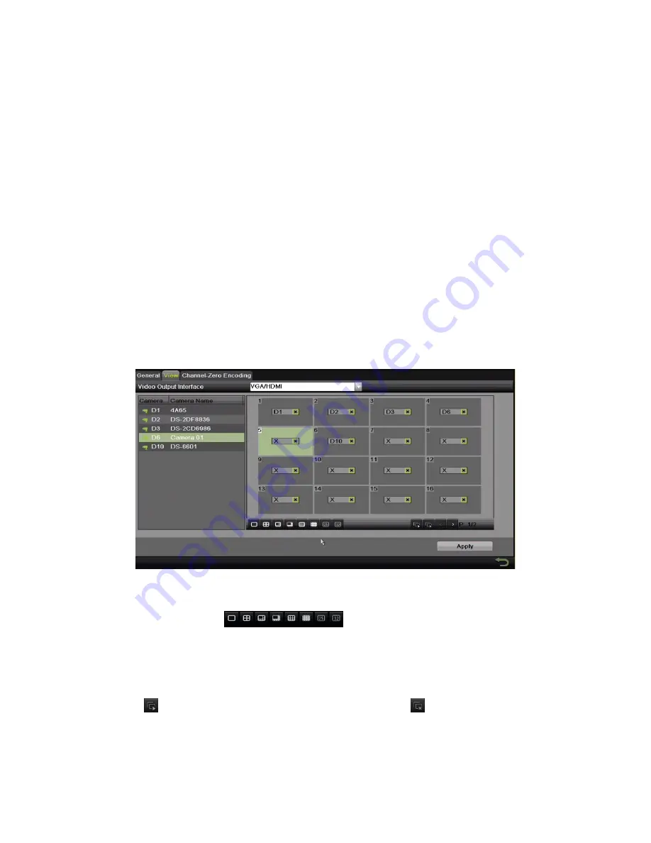
Set Camera Order.
Figure 46 Live View, Camera Order
1) Select a View mode in
, including 1/4/6/8/16/25/32/36/64-window division modes,
which are supported depending on model.
2) Select the small window, and double-click the channel number to display the channel on the window.
3) Click
button to start live view for all the channels and click
to stop all live views.
4) Click the Apply button to save the setting.
NOTE:
You can also click-and-drag the camera to the desired window on the live view interface to set the
camera order.